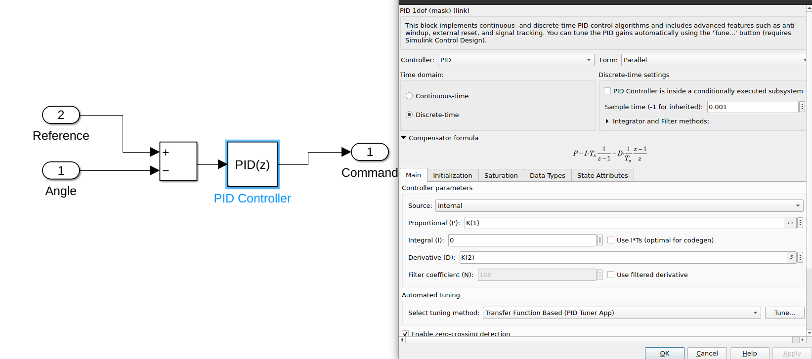
I am trying to match the trajectory i am getting from gazebo simulation using ros_control and matlab for a simple pendulum which rotates in the horizontal plane (so no gravity, no friction and no mechanical reductions).
The Dynamics are governed by the following equation: $$ I\ddot{q} = u $$ where u is the input signal, and $I = 2.4667 \ kgm^2$.
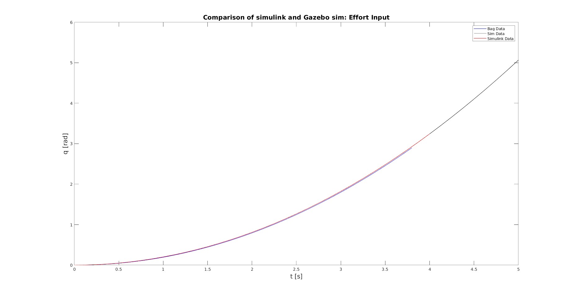
When $u(t) = u(0)$ (step input. I am using the joint_effort_controller in gazebo in this case) the simulations are close enough, as it can be seen from the following graph.
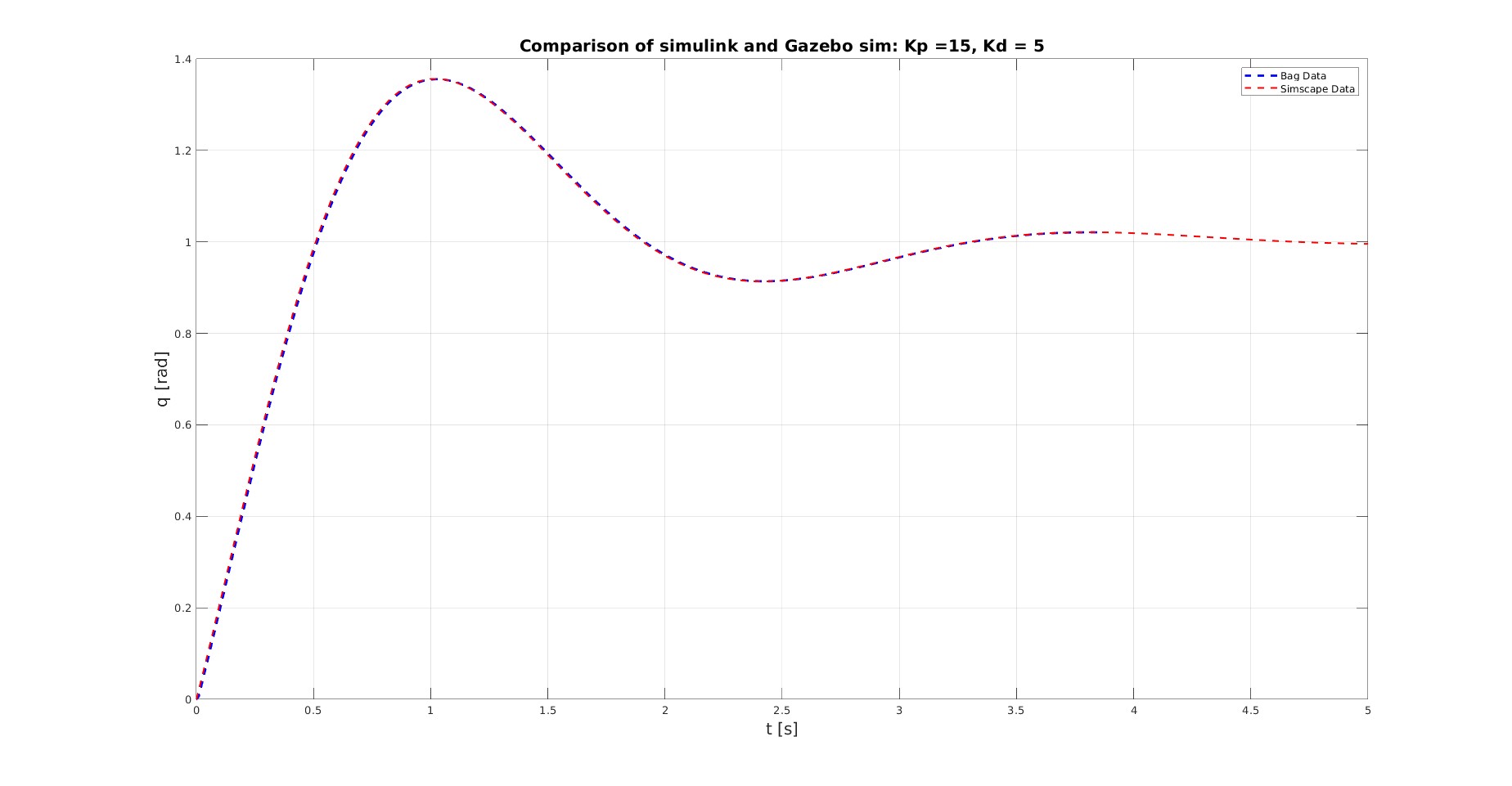
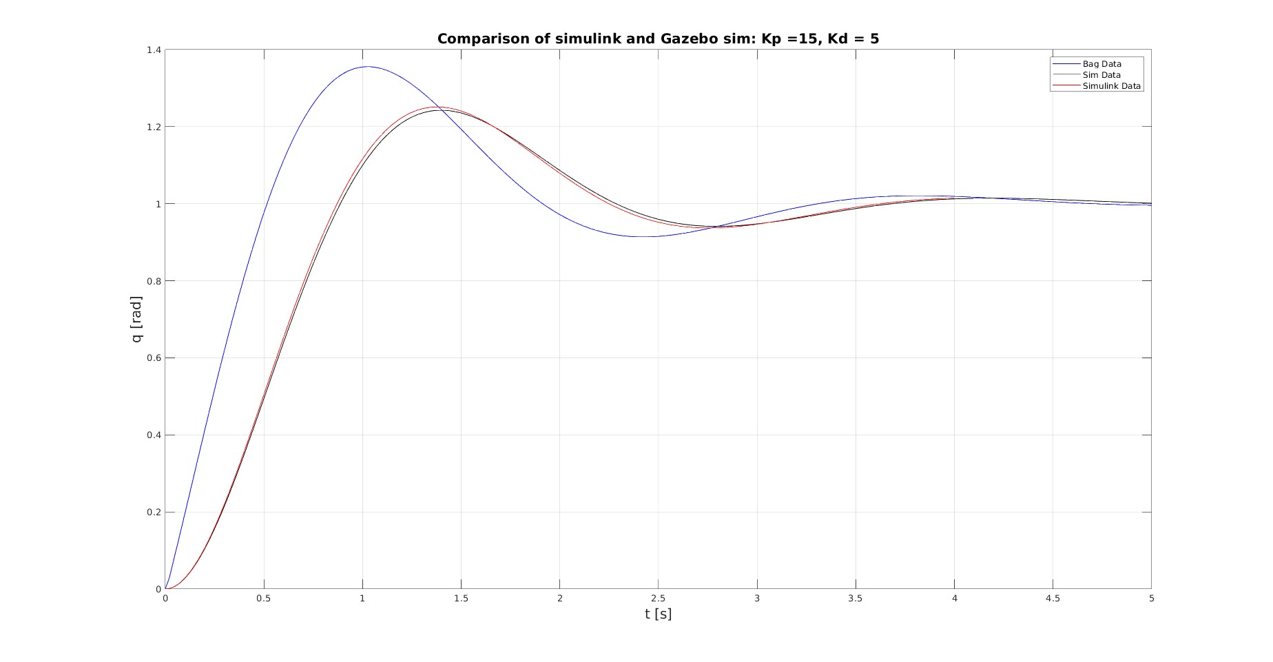
However when i use a pid to control the position (using an effort_controllers/JointPositionController) there are major differences. They can been seen in the following graph:
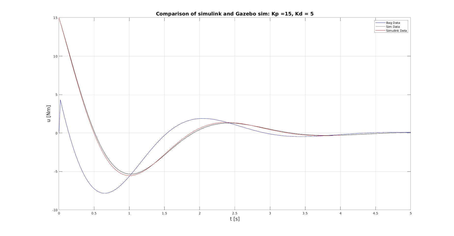
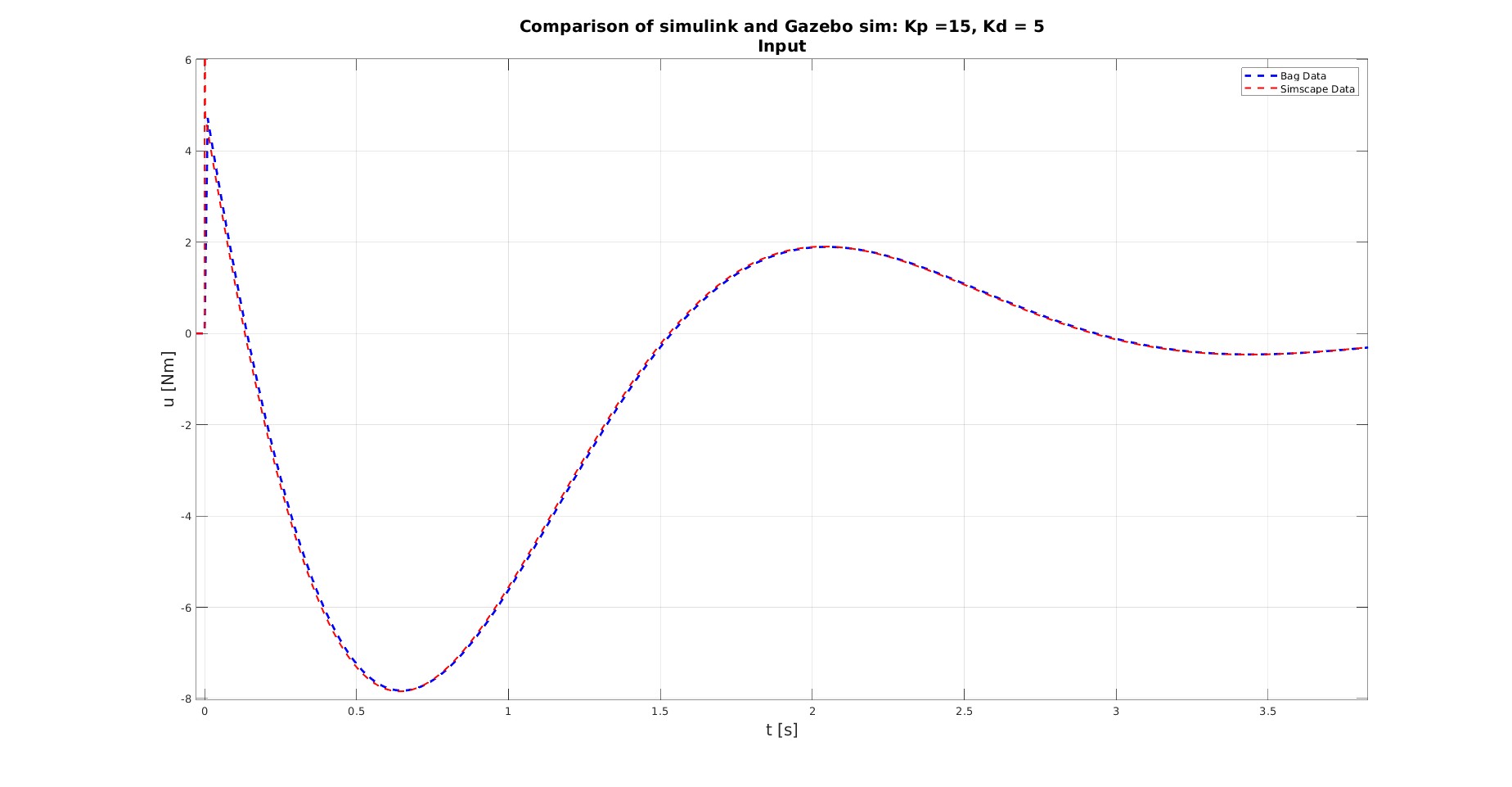
The culprit seems to be the input, as it is considerably different:
The pid gains are chosen as follows:
pid: {p: 15, i: 0.00, d: 5.0}
In theory, the initial command is ($q_d=1$, and $\{ q_0,\dot{q}_0 \} = \{0,0\}$ ) $$ u_0 = Kp(q_d-q_0) + Kd(0-\dot{q}_0) = 15+0 = 15Nm $$
Matlab gives the expected initial input, however, the commanded torque from ros_control is $u_0 \approx 4 Nm$.
Question I cannot explain how the input command gets that value. And as a result how ros_control calculates the input signal. Any help, hint or idea about what causes this difference will be of great help.
Update Without the derivate term, and only $K_p = 15$ the initial input matches the theoretical one, so $u_0 = 15Nm$. However, from the implementation as it is discussed below:
$$ p_{error} = p_{state}-p_{desired} -> e_{position,0} = -1;$$ $$ d_{error} = (p_{error}-p_{error_last})/T -> e_{velocity,0} = -1/T;$$ I would expect the initial input to be something like that:
$$ u_{ros,0} = -15(-1) -5(-1/T) = 15+5/T$$
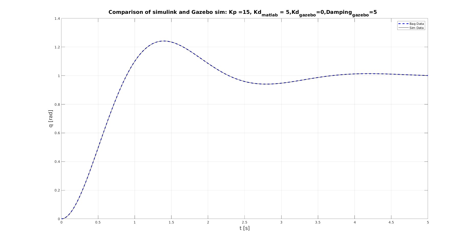
Update 2 If the derivate gain is set to zero, and instead i add damping of 5Ns/rad, then the results between matlab and gazebo match. It can be seen in the next figure.
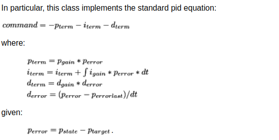
Extra1 I have to mention that looking the control tooblox API which is used by ros_control for the pid controller, the from of the PID controller is of the following form:
(see lines 331 in the pid.cpp where the function computeCommand is defined. )
Extra2 $$\dot{e}_{position} = \frac{d}{dt}(q_d-q) = -\dot{q} $$
Extra3 The settings for the controller are:
  joint1_position_controller:
    type: effort_controllers/JointPositionController
    joint: base_to_link1
    pid: {p: 15, i: 0.00, d: 5.0}
    publish_rate: 50
