Remember that the columns of a rotation matrix are simply unit vectors indicating where each axis points. Lets say your end-effector is at $p_e = (x_e, y_e, z_e)$, and the center of the circle is at $p_o = (x_o, y_o, z_o)$. You didn't fully answer my comment about your end-effector axes, so I will assume you want $z_e$ pointed at the object. Here are the steps you should take.
First, some notation. The transform from the world frame to your desired end-effector is:
$$
T^{world}_{ee} = \begin{bmatrix} R_e & p_e \\ 0 & 1 \end{bmatrix}
$$
Where $R_e$ is the rotation matrix in question. It is composed of 3 column vectors:
$$
R_e = \begin{bmatrix} R_{x_e} & R_{y_e} & R_{z_e} \end{bmatrix}
$$
- The third (Z) column of the rotation matrix is simply $R_{z_e} = \widehat{p_o - p_e}$.
- Pick a natural orientation for your camera. Perhaps $y_e$ down. So think about a plane created by the world down axis and $R_{z_e}$. Now $x_e$ must be normal to that plane. Assuming the world down axis is $down = (0,0,-1)$. Now $R_{x_e} = \widehat{down \times R_{z_e}}$. This is the first (X) column of your rotation matrix. (Note: be careful to avoid degenerate cases, like when the camera is directly above the object ($z_e = z_o$). You need to test for this case and handle this differently.)
- Lastly, the Y axis of your new frame must be the cross product of the other two, so: $R_{y_e} = R_{z_e} \times R_{x_e}$. This is the second (Y) column of your new rotation matrix.
This gives you a single orientation for each position on your sphere in which the object will be upright in the camera image.
Your question was a little vague on whether this is sufficient, or if you want many orientations for each point on the sphere. Since the camera can rotate about its focal axis, the arm and camera will still be pointing at the object. However, the object will be rotated in the image.
There are an infinite number of orientations that satisfy the constrains for each point, but you can get a discrete set by picking some angles from 0 to 360 degrees then simply rotating your end-effector frame about its Z axis by this amount.
$$
T^{world}_{newee} = T^{world}_{ee} * \begin{bmatrix}
\cos \theta & -\sin \theta & 0 & 0\\
\sin \theta & \cos \theta & 0 & 0\\
0 & 0 & 1 & 0\\
0 & 0 & 0 & 1\\
\end{bmatrix}
$$
So now $T^{world}_{newee}$ will have the object upside down if you chose $\theta = 180^{\circ}$ for example.
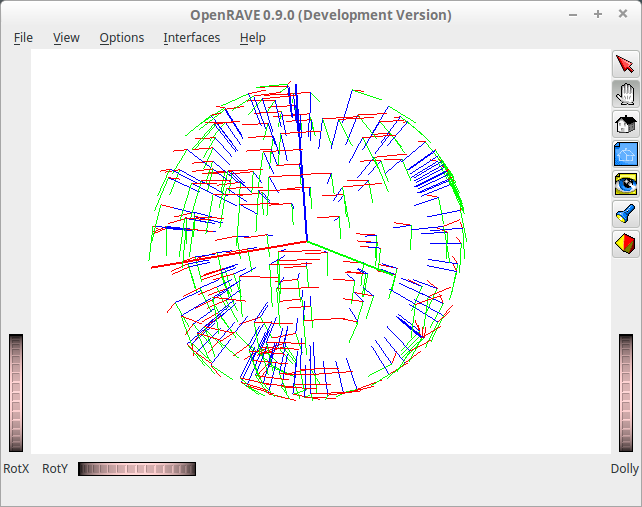
Here is some simple Python code which implements this solution (without the arbitrary rotation), and displays the frames with OpenRave.
#! /usr/bin/env python

import numpy as np
from openravepy import *

# set up OpenRave environment
env = Environment()
env.SetViewer('qtcoin')

# center of sphere
p_o = np.array([0.0, 0.0, 0.0])

# radius of sphere
r = 1.0

# down vector
down = np.array([0.0, 0.0, -1.0])

# large coordinate frame at the center of the sphere
originaxes = misc.DrawAxes(env, [1, 0, 0, 0, p_o[0], p_o[1], p_o[2]], dist=1, linewidth=2)

# all other frames
axes = []

for i in range(200):

    # get a random point on the sphere
    p_e = np.random.uniform(-1, 1, 3)
    p_e *= r / np.linalg.norm(p_e)
    p_e += p_o

    # Z column
    R_z = (p_o - p_e)
    R_z /= np.linalg.norm(R_z)

    # X column
    R_x = np.cross(down, R_z)
    R_x /= np.linalg.norm(R_x)

    # Y column
    R_y = np.cross(R_z, R_x)

    # Full transformation matrix
    T = np.array([[ R_x[0], R_y[0], R_z[0], p_e[0] ],
                  [ R_x[1], R_y[1], R_z[1], p_e[1] ],
                  [ R_x[2], R_y[2], R_z[2], p_e[2] ],
                  [      0,      0,      0,      1]])

    # draw it
    axes.append(misc.DrawAxes(env, T, dist=0.2, linewidth=1))
This should give you frames all around the sphere like this:


