2
$\begingroup$

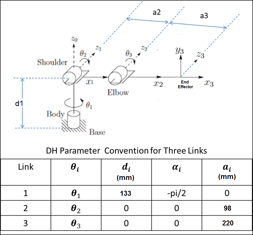
I have a robotic arm consist of three joints (servomotor for each joint), as shown in the figure below:

enter image description here

Notes:

Each servomotor rotates around 180 degrees.

The angles of the theta2 and theta3 represent 90 degrees in the figure above.

I found the forward kinematics by using the parameters of DH convention, as shown in the figure above.

The Final Transformation Matrix is:

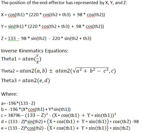
enter image description here

enter image description here

The position of the robotic arm end-effector is correct for any angle of theta1, theta2, and theta3 between -90 and 90 degrees.

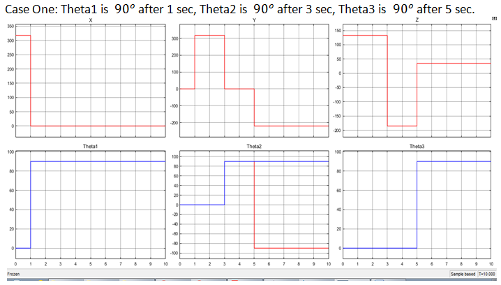
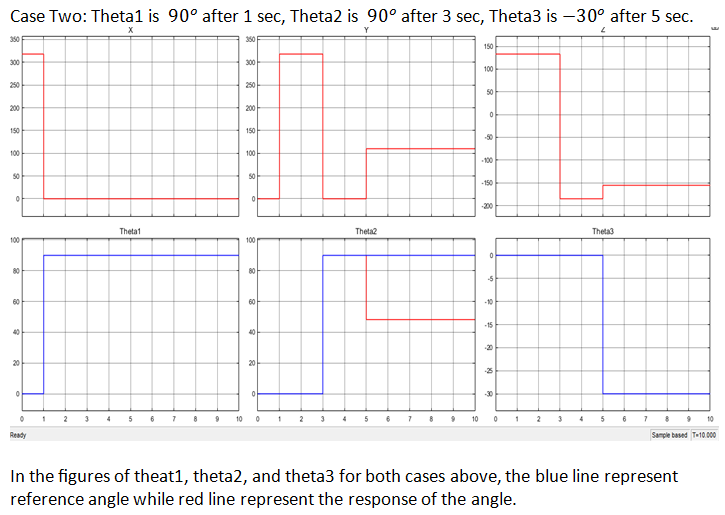
My problem is in the inverse kinematics of the robotic arm, where, the theta2 always affected by theta3 and thus the response of theta2 incorrect, while theta1 and theta3 are always correct. Please see the cases below that show this problem.

enter image description here

enter image description here

Thank you.

$\endgroup$

3 Answers 3

1
$\begingroup$

I’ll get you started, and see if you can calculate all three joint angles given values for $X$, $Y$, and $Z$. If you cannot, we can continue peeling the onion until you are able to do that.

You will have to manipulate the expressions for $X$, $Y$, and $Z$, and use trigonometric identities to solve for the individual joint values.

Start with the easiest: using the $X$ and $Y$ terms only, you should be able to write an expression that only involves th1. It will be a tangent function that can be inverted to find th1.

Next, square the $X$ and $Y$ terms, and add them together. This will eliminate th1 from the expression. Subtract $Z$ squared from the remaining terms. You should be left with expressions of a constant times [cos(th2 + th3) cos(th2) + sin(th2 + th3) sin(th2)]. Using a trigonometric identity, this can be solved for th3 using the inverse cos function.

See if you can get to this point, then try other manipulations to solve for (th2 + th3), which will get you the last value.

$\endgroup$
3
  • $\begingroup$ thank you for your reply, but I solved my problem by using the geometry approach and also I got the same results. $\endgroup$
    – B. Antony
    Commented Feb 6, 2019 at 5:48
  • $\begingroup$ Great answer, it is possible to calculate the inverse kinematics without getting in touch with a real computer or real software projects. The answer explains the problem on a theoretical basis with a strong focus on algebra transformation. This avoids to raise detail problems which are happening while implementing the code in Python programming language or in a 3d physics engine. $\endgroup$ Commented Feb 6, 2019 at 10:05
  • $\begingroup$ @B.Antony, the geometric approach is also a great way to solve this problem. Good job. $\endgroup$
    – SteveO
    Commented Feb 6, 2019 at 20:53
0
$\begingroup$

I think the debate is a bit off topic. To me, the question is about why is the inverse kinematics wrong when applied to a forward kinematics solution computed for joint angles $\ge$ 90 deg.

To explore this I built a model using my Robotics Toolbox for MATLAB

>> r = SerialLink([0 133 0 -pi/2; 0 0 98 0; 0 0 220 0])
r = 

noname:: 3 axis, RRR, stdDH, fastRNE                             
+---+-----------+-----------+-----------+-----------+-----------+
| j |     theta |         d |         a |     alpha |    offset |
+---+-----------+-----------+-----------+-----------+-----------+
|  1|         q1|        133|          0|    -1.5708|          0|
|  2|         q2|          0|         98|          0|          0|
|  3|         q3|          0|        220|          0|          0|
+---+-----------+-----------+-----------+-----------+-----------+

then I computed the forward kinematics for the first and last joint configurations in @B.Antony's question:

>> r.fkine([0 0 0])
ans = 
         1         0         0       318
         0         0         1         0
         0        -1         0       133
         0         0         0         1

>> T = r.fkine([90 90 90], 'deg')
T = 
         0         0        -1         0
        -1         0         0      -220
         0         1         0        35
         0         0         0         1

and the answers match what's in the graphs provided. So far, so good.

Ignoring the debate about analytical versus numerical solutions I'm going to use a numerical solution since it's general and I have it to hand:

>> q = r.ikine(T, 'mask', [1 1 1 0 0 0])
q =
   -1.5708   -0.7327    1.5708

where mask indicates that we only care about solving for the first 3 elements of the Cartesian pose (x,y,z).

We see this solution is different to what was input to the forward kinematics and it has flipped $\theta_1$ around, but we can easily verify that the solution is correct

>> r.fkine(q)
ans = 
         0         0         1         0
   -0.6689    0.7434         0      -220
   -0.7434   -0.6689         0        35
         0         0         0         1

Note: the translation part is correct, the rotation part is different but we don't have enough DoF to independently control that.

We can try and find a solution with a positive $\theta_1$ by setting the initial joint angles for the IK

>> r.ikine(T, 'mask', [1 1 1 0 0 0], 'q0', [pi/2 0 0])
ans =
    1.5708    1.5708    1.5708

which is the set of joint angles we started with, so this is another valid solution, the blue line in the graph.

I don't think the red solution shown in the graph of $\theta$ values is correct

>> r.fkine([90 -90 90], 'deg')
ans = 
         0         0        -1         0
         1         0         0       220
         0        -1         0       231
         0         0         0         1

is far from the initial pose shown above.

Conclusion the IK equations implemented are not correct. There should be at least 4 solutions: 2 for q1 (you have only 1), and 2 for q2 (which you have). Maybe another set of 4 where $\theta_2$ and $\theta_3$ are offset by 180deg.

I can automatically generate an analytic solution (you need the MATLAB Symbolic Math Toolbox to do this bit)

>> q = r.ikine_sym(3)
----- solving for joint 1
subs sin/cos q1 for S/C
----- solving for joint 2
lets square and add 1 2
subs sin/cos q2 for S/C
----- solving for joint 3
subs sin/cos q3 for S/C
**final simplification pass

q =
  1×3 cell array
    {1×2 sym}    {1×2 sym}    {1×2 sym}

Looking at the solution for $\theta_1$

>> q{1}
ans =
[ atan2(-ty, -tx), atan2(ty, tx)]

we can see the two solutions.
$\endgroup$
-3
$\begingroup$

Calculating the forward kinematics with a mathematical equation is straight forward and recommended for all robotics arms. Trying to do the same with inverse kinematics results often in troubles. The problem is, that a given goal coordinate in the 3d space can be reached with different poses and during it's nonlinear nature it's not easy to find an explicit formula. The problem is, that a forward model can't be transformed into an inverse model by simply modifying the equation into a new one. Instead an approximate IK-solver is needed here.

For realizing such a solver the forward model gets random values as input and the best node of the resulting graph is identified with the help of constraints. The principle is called monte carlo IK solver or sampling based ik solver and is a standard widget in animation programs like Blender.

Perhaps a short note at the end: even the problem looks easy to solve on the first look, inverse kinematics is one of the hardest problems in robotics control. Running into trouble is the normal case and Google Scholar provides many thousands of papers about the pros and cons of different solvlng techniques. For some researchers the problem is so hard, that they give up the idea of a kinematic chain at all and use a more simpler mechanic design which is a linear robot. Such a design can reach a point in the space with lower amount of calculations.

$\endgroup$
6
  • 2
    $\begingroup$ The inverse kinematics for this manipulator are calculatable in closed-form, and have been published in many places. Iterative solutions are not needed for this 3DOF arm. $\endgroup$
    – SteveO
    Commented Feb 5, 2019 at 23:58
  • $\begingroup$ I concur with @SteveO when he says that for a 3DOF chain we shall use closed-form solution. Further, IK is not the hardest problem in Robotics since long by now; rather, it can be considered solved by resorting to: closed-form solutions, classical iterative Jacobian-based methods and optimization techniques. $\endgroup$ Commented Feb 6, 2019 at 9:11
  • $\begingroup$ I'm sorry, that my answer isn't oriented on the closed form inverse kinematics, which is the easiest one to implement. The problem is, that I'm focussed on practical coding in real projects. Even in a 2d environment without a physics engine i recommend the iterative solution, because I'm interested in results and not in beautiful mathematics. It's my fault. $\endgroup$ Commented Feb 6, 2019 at 10:12
  • $\begingroup$ I have implemented closed-form inverse kinematics equations as part of practical, real-world programs for 6 and 8 DOF systems. I don’t understand where you are coming from. But that’s probably tangential to this topic. $\endgroup$
    – SteveO
    Commented Feb 6, 2019 at 20:51
  • $\begingroup$ Please try to be nice, there is no need for anyone to snippy or sarcastic. I shouldn't need to deal with flags that comments are "unfriendly or unkind". For specific guidelines, see our Code of Conduct. $\endgroup$
    – Mark Booth
    Commented Feb 20, 2019 at 10:19

Your Answer

By clicking “Post Your Answer”, you agree to our terms of service and acknowledge you have read our privacy policy.

Not the answer you're looking for? Browse other questions tagged or ask your own question.