6
$\begingroup$

I want to find the instantaneous center of rotation of a differential drive robot.

Assuming I know that the robot will travel with a particular linear and angular velocity $(v,w)$ I can use the equations (given at A Path Following a Circular Arc To a Point at a Specified Range and Bearing) which come out to be:

$$x_c = x_0 - |\frac{v}{w}| \cdot sin(\theta_0)$$ $$y_c = y_0 - |\frac{v}{w}| \cdot cos(\theta_0) $$

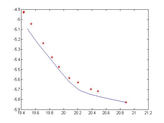
I'm using the webots simulator and I dumped gps points for the robot moving in a circle (constant v,w (1,1)) and instead of a single $x_c$ and $y_c$ I get a center point for every point. If I plot it out in matlab it does not look nice:

circles.jpg

The red points in the image are the perceived centers, they just seem to trace the curve itself.

Is there some detail I am missing? I'm really really confused as to what's happening.

I'm trying to figure out the center so I can check whether an obstacle is on this circle or not and whether collision will occur.
$\endgroup$
0

2 Answers 2

2
$\begingroup$

It's hard to see what's going on exactly, especially without seeing the code or knowing more about the sensor model. That's said, your trajectory is mostly straight and $w$ is thus mostly close to zero. This means that:

  • your center of rotation is far away during most of your experiment -- likely beyond the bounds of your graph;
  • you may have numerical stability issues due to a division by a very small number.
$\endgroup$
1
  • $\begingroup$ I adjusted for the size of the robot assuming that the location/coordinates of the robot point to the center and since its a differential drive robot the radius must be half the wheel distance ... So now I get something like this docs.google.com/file/d/0BzLnU1-OKHh7eDZKd3hlUGRwekE/… The points come out to be close enough but the center s are just so off. I didn't plot the centers as individual points though. Do you think its because w is too small ? if w is 1 it isnt much too small right? So should I should focus on the coordinate sensor model ? $\endgroup$
    – canatan
    Commented Jun 4, 2013 at 19:33
0
$\begingroup$

It looks like there is some noise in the sensor readings. Make sure your simulator is reporting ground truth, or you have some tolerance to noise.

See here: http://www.cyberbotics.com/dvd/common/doc/webots/guide/section9.2.html

In particular

In Supervisor code:

To get the 3D position of any Transform (or derived) node in the Supervisor code: you can use the wb_supervisor_node_get_position() function. Please check this function's description in the Reference Manual.

To get the 3D position of any Transform (or derived) node placed at the root of the Scene Tree (the nodes visible when the Scene Tree is completely collapsed), you can use the wb_supervisor_field_get_sf_vec3f() function. Here is an example.

A simulation example that shows both the GPS and the Supervisor techniques is included in the Webots installation, you just need to open this world: $WEBOTS_HOME/projects/samples/devices/worlds/gps.wbt.


IF in fact noise in the state estimate is the problem (bit IF), then the way to compensate for such errors is to use an estimate of your state and error models. It's beyond the scope of the question, unfortunately. If you want to do obstacle avoidance AND you are certain that sensor error is the issue, I suggest you:

  1. Check for obstacles in a wide band (a fat circle) which could represent your trajectory with a bit of error

  2. Run a filter to get an estimate of robot position, then find the "likely" collisions

  3. Only look for obstacles over a small window into the future. In the short term, your state estimate should be fine.

However, these are heavy handed fixes for what is likely a small problem.

$\endgroup$
5
  • $\begingroup$ Thanks @Josh. The webots part is not what I'm supposed to really touch but I'll definitely look into it. There is a ROS interface I'm using for this robot and the webots simulator. Even if there is some sensor noise my estimates should be close to each other right ? In some cases I trace a complete circle with say v and w as 1 and 1 but the center was so off. Is it just the sensor noise or is there something wrong with the math I'm using ? Does the instantaneous center of rotation keep changing even if the velocities don't change? if its just noise is there some way I can account for it? $\endgroup$
    – canatan
    Commented Jun 3, 2013 at 16:48
  • $\begingroup$ No the ICR doesn't change if V, W, and the robot position at time i+1 = exactly the position at time i + the correct update from V, W. If you nudge the new position a bit, the ICR will change. A small angular error could result in a big change in ICR for large circles. $\endgroup$ Commented Jun 3, 2013 at 21:34
  • $\begingroup$ Thank you @Josh. is there any way I can compensate for such errors ? I'm trying to implement the collision detection as in the dynamic window approach and using the distance between the obstacle and the ICC to figure out whether a point is on that circle or not. $\endgroup$
    – canatan
    Commented Jun 4, 2013 at 2:42
  • $\begingroup$ I've edited the question a bit. $\endgroup$ Commented Jun 4, 2013 at 2:59
  • $\begingroup$ Thanks Josh. I was trying to use the ICC to determine whether or not the obstacle lies on that curve by calculating the distance between the ICC and the obstacle and comparing it with the radius (v/w). Does that seem like a valid option in such a case ? $\endgroup$
    – canatan
    Commented Jun 4, 2013 at 19:52

Your Answer

By clicking “Post Your Answer”, you agree to our terms of service and acknowledge you have read our privacy policy.

Not the answer you're looking for? Browse other questions tagged or ask your own question.