Stripped the original equation now the MathJax has been confirmed.
Source Link
Mark Booth
  • 4.3k
  • 2
  • 26
  • 56

I want to find the instantaneous center of rotation of a differential drive robot.

Assuming I know that the robot will travel with a particular linear and angular velocity $(v,w)$ I can use the equations (given at A Path Following a Circular Arc To a Point at a Specified Range and Bearing) which come out to be:

$$x_c = x_0 - |\frac{v}{w}| \cdot sin(\theta_0)$$ $$y_c = y_0 - |\frac{v}{w}| \cdot cos(\theta_0) $$

x_c = x_0 - abs(v/w) sin(\theta_0)
y_c = y_0 - abs(v/w) cos(\theta_0) 

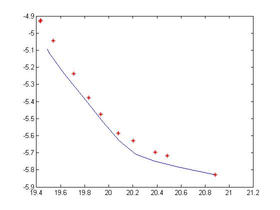
I'm using the webots simulator and I dumped gps points for the robot moving in a circle (constant v,w (1,1)) and instead of a single $x_c$ and $y_c$ I get a center point for every point. If I plot it out in matlab it does not look nice:

circles.jpg

The red points in the image are the perceived centers, they just seem to trace the curve itself.

Is there some detail I am missing? I'm really really confused as to what's happening.

I'm trying to figure out the center so I can check whether an obstacle is on this circle or not and whether collision will occur.

I want to find the instantaneous center of rotation of a differential drive robot.

Assuming I know that the robot will travel with a particular linear and angular velocity $(v,w)$ I can use the equations (given at A Path Following a Circular Arc To a Point at a Specified Range and Bearing) which come out to be:

$$x_c = x_0 - |\frac{v}{w}| \cdot sin(\theta_0)$$ $$y_c = y_0 - |\frac{v}{w}| \cdot cos(\theta_0) $$

I'm using the webots simulator and I dumped gps points for the robot moving in a circle (constant v,w (1,1)) and instead of a single $x_c$ and $y_c$ I get a center point for every point. If I plot it out in matlab it does not look nice:

circles.jpg

The red points in the image are the perceived centers, they just seem to trace the curve itself.

Is there some detail I am missing? I'm really really confused as to what's happening.

I'm trying to figure out the center so I can check whether an obstacle is on this circle or not and whether collision will occur.

Tweeted twitter.com/#!/StackRobotics/status/341374659327062016
Tidied up the superfluous commentary and added what I believe to be the MathJax for the given equations.
Source Link
Mark Booth
  • 4.3k
  • 2
  • 26
  • 56

I'm hoping this is the right place to post this because stackoverflow is always helpful. If its not please let me know where I can.

I want to find the instantaneous center of rotation of a differential drive robot. 

Assuming I know that the robot will travel with a particular linear and angular velocity (v,w)$(v,w)$ I can use the equations (given hereat http://rossum.sourceforge.net/papers/CalculationsForRobotics/CirclePath.htmA Path Following a Circular Arc To a Point at a Specified Range and Bearing  ).

which come out to be:

x_c = x_0 - abs(v/w) sin(\theta_0)$$x_c = x_0 - |\frac{v}{w}| \cdot sin(\theta_0)$$ y_c = y_0 - abs(v/w) cos(\theta_0)$$y_c = y_0 - |\frac{v}{w}| \cdot cos(\theta_0) $$

x_c = x_0 - abs(v/w) sin(\theta_0)
y_c = y_0 - abs(v/w) cos(\theta_0) 

I'm using the webots simulator and I dumped gps points for the robot moving in a circle (constant v,w (1,1)) and instead of a single x_c$x_c$ and y_c$y_c$ I get a center point for every point. ifIf I plot it out in matlab it does not look nice.:

Here's an image ...circles.jpg

theThe red points in the image are the perceived centers

https://docs.google.com/file/d/0BzLnU1-OKHh7dmxvbGU1bDFKcFU/edit?usp=sharing

, they just seem to trace the curve itself.

isIs there some detail I am missing  ? I'm really really confused as to whatswhat's happening.

help please

I'm trying to figure out the center so I can check whether an obstacle is on this circle or not and whether collision will occur.

I'm hoping this is the right place to post this because stackoverflow is always helpful. If its not please let me know where I can.

I want to find the instantaneous center of rotation of a differential drive robot. Assuming I know that the robot will travel with a particular linear and angular velocity (v,w) I can use the equations (given here http://rossum.sourceforge.net/papers/CalculationsForRobotics/CirclePath.htm  ).

which come out to be

x_c = x_0 - abs(v/w) sin(\theta_0) y_c = y_0 - abs(v/w) cos(\theta_0)

I'm using the webots simulator and I dumped gps points for the robot moving in a circle (constant v,w (1,1)) and instead of a single x_c and y_c I get a center point for every point. if I plot it out in matlab it does not look nice.

Here's an image ...

the red points in the image are the perceived centers

https://docs.google.com/file/d/0BzLnU1-OKHh7dmxvbGU1bDFKcFU/edit?usp=sharing

they just seem to trace the curve itself.

is there some detail I am missing  ? I'm really really confused as to whats happening.

help please

I'm trying to figure out the center so I can check whether an obstacle is on this circle or not and whether collision will occur.

I want to find the instantaneous center of rotation of a differential drive robot. 

Assuming I know that the robot will travel with a particular linear and angular velocity $(v,w)$ I can use the equations (given at A Path Following a Circular Arc To a Point at a Specified Range and Bearing) which come out to be:

$$x_c = x_0 - |\frac{v}{w}| \cdot sin(\theta_0)$$ $$y_c = y_0 - |\frac{v}{w}| \cdot cos(\theta_0) $$

x_c = x_0 - abs(v/w) sin(\theta_0)
y_c = y_0 - abs(v/w) cos(\theta_0) 

I'm using the webots simulator and I dumped gps points for the robot moving in a circle (constant v,w (1,1)) and instead of a single $x_c$ and $y_c$ I get a center point for every point. If I plot it out in matlab it does not look nice:

circles.jpg

The red points in the image are the perceived centers, they just seem to trace the curve itself.

Is there some detail I am missing? I'm really really confused as to what's happening.

I'm trying to figure out the center so I can check whether an obstacle is on this circle or not and whether collision will occur.

Source Link
canatan
  • 101
  • 4
Loading