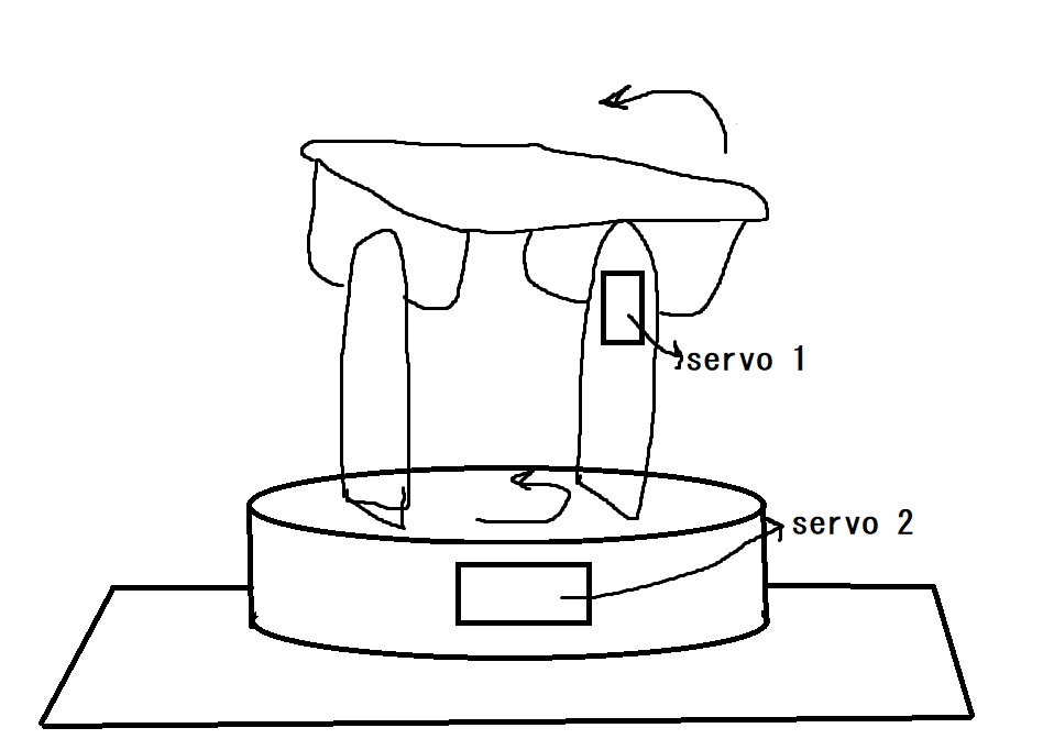
I design a solar tracking mechanisim. You can see the very undetailed representation in the pic. For choosing a servo motor how can I calculate the torque etc?
-
$\begingroup$ why would you need a servo? ... a constant RPM motor would be sufficient $\endgroup$– jsotolaCommented Apr 25, 2021 at 21:23
-
$\begingroup$ I did not use any other types of motor before. This is the only reason. $\endgroup$– HollyPollyCommented Apr 26, 2021 at 6:36
2 Answers
Most solar tracking rigs only move along one axis because the efficiency savings from moving along 2 doesn't make up for the energy losses of having 2 motors.
If you're just doing this for fun, then you have questions to ask yourself:
- How heavy is the system that you're moving?
- Is it so heavy that a normal hobby servo couldn't handle it?
- Is this application better suited for something like a large brushless motor & an O-Drive?
You really didn't provide a ton of detail here, so it's hard to help with motor selection.
-
$\begingroup$ thanks for first information i didnt knew that and I am doing this for fun. Its size will be only like a laptop so it is not be much heavy. I just want to learn how to do calculations about choosing a motor. $\endgroup$ Commented Apr 25, 2021 at 19:41
Servo 1. Referring to your diagram, first consider the tilting part at the top. Imagine a line connecting its bearings. It will tilt (rotate) about that axis. The weight (force due to gravity) of the top part can be modeled as a single point, located at the Center of Gravity. The force, pointing straight down, tries to make the top part flop over -- it will exert a torque around the axis. To keep things stable, the servo has to exert a, equal but opposite torque.
That torque will be $T = F\ r\ sin\ \theta$ where
- $T$ is the torque
- $F$ is the weight of the top part.
- $r$ is the distance of the CoG from the axis.
- $\theta$ is the angle that the tabletop surface makes with the horizontal.
If things are sufficiently symmetrical, the CoG will be directly above the axis when the top surface is perfectly level. Then, $\sin \theta = 0$ so $T = 0$. When it tilts so far that the surface becomes vertical (assuming that it's not obstructed somehow), $\sin \theta = 1$ and the torque is at the max.
The rest of your design will determine the max angle -- you might have some stops or bumpers or something. Plug that max angle, along with the weight and dimensions, into the formula above.
But wait, there's more. The servo has to do more than just hold the mechanism still. It has to move it. That means it has to exert additional torque to overcome friction, which we can't calculate here because it depends on the sort of bearings you design in. Also, in general, the servo has to accelerate the mass to start it moving, and decelerate to stop it -- but that will be negligible if you're just tracking the sun.
Servo 2 is a lot simpler, because the vertical rotation axis is always parallel with gravity. You have friction (mitigated by a lazy-susan bearing or something) and acceleration (as above). Again, there's no good way to calculate it here.
For prototyping with relatively inexpensive things like hobby servos, we typically specify torques lots beefier than the theoretical calculations suggest. If you were moving a multi-ton radio telescope dish, the engineering gets a lot more involved.
