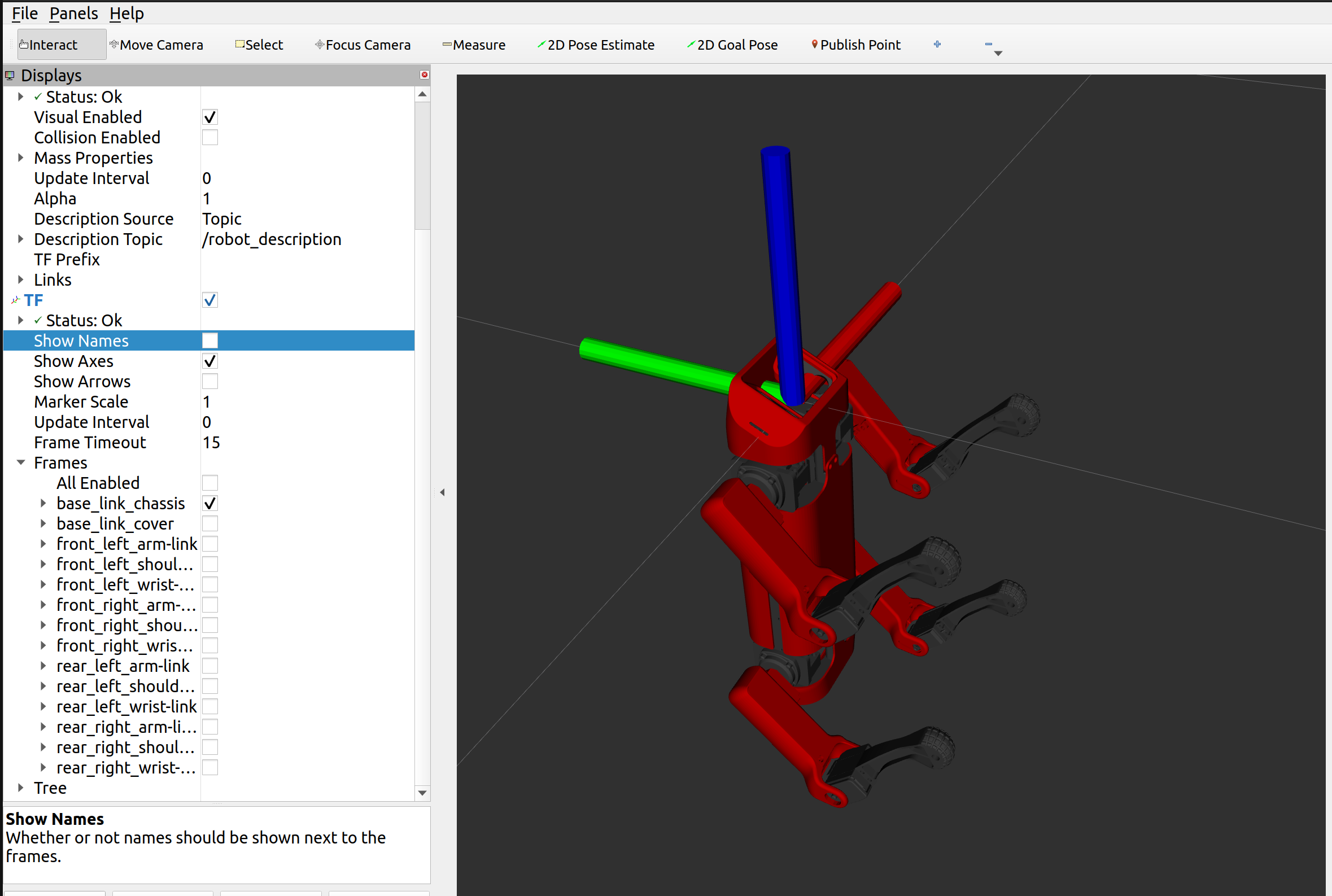
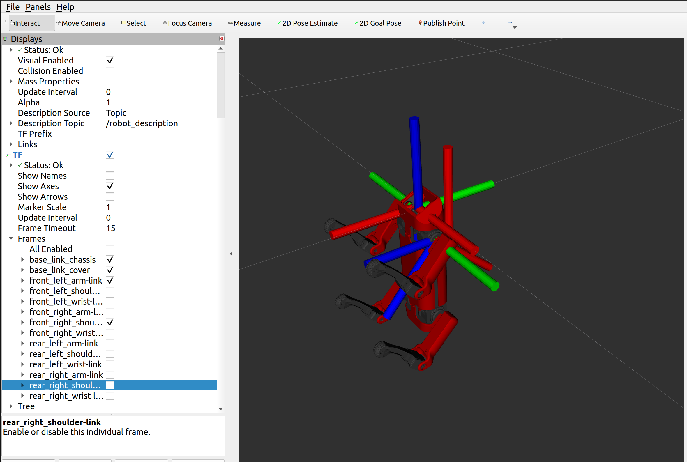
I don't have that much experience with URDF but I think a feasible solution would be to create another link called base_link as a parent of the main frame of your current model (I guess base_link_chassis).
In the joint between the two frames, you could define the rotation needed to get your model parallel to the floor plane. The X axis (red) of base_link should point forward in the robot preferred direction of movement, the Y axis to the left (green) and the Z axis (blue) upwards.
Additionally, make sure that base_link is centered according to the robot model (or in a position that makes things easier for your specific application). Usually, a centered base_link makes navigation tasks easier, as you can assume a robot radius instead of the robot footprint.
However, if you find the time in a future, try to clean the frame tree and give to each of the links a meaning for its position and orientation.
For more specific conventions related to coordinate frames, you can refer to this REP.
Besides the physical meaning of links when it refers to robot movement, you can also think about links more broadly as change in coordinate system. That is what you want to achieve in your application, you want to change how the model looks like according to a given reference system. Instead of changing all the links orientation, we could add another reference system where you include this rotation.
I'll use as a base example some of the urdf of the URDF tutorials, specifically the Origins example. You can also take a look to the rest of the URDFs used here.
The urdf looks like this:
<?xml version="1.0"?>
<robot name="origins">
  <link name="base_link">
    <visual>
      <geometry>
        <cylinder length="0.6" radius="0.2"/>
      </geometry>
    </visual>
  </link>

  <link name="right_leg">
    <visual>
      <geometry>
        <box size="0.6 0.1 0.2"/>
      </geometry>
      <origin rpy="0 1.57075 0" xyz="0 0 -0.3"/>
    </visual>
  </link>

  <joint name="base_to_right_leg" type="fixed">
    <parent link="base_link"/>
    <child link="right_leg"/>
    <origin xyz="0 -0.22 0.25"/>
  </joint>

</robot>
It consists of 2 links (base_link and right_leg) with visual information and 1 joint (base_to_right_leg) that joins both of them with a given distance (as defined in <origin xyz="0 -0.22 0.25"/>).
We can add an additional link (added_base) to become the root link as in the following example:
<?xml version="1.0"?>
<robot name="origins">

  <!-- New link with no visual information -->
  <link name="added_base">
  </link>

  <!-- New joint that defines rotation and positioning -->
  <joint name="added_base_to_base_link" type="fixed">
    <parent link="added_base"/>
    <child link="base_link"/>
    <!-- Define rotation and positioning here -->
    <origin  rpy="0 1.57075 0" xyz="0 -0.22 0.25"/>
  </joint>

  <link name="base_link">
    <visual>
      <geometry>
        <cylinder length="0.6" radius="0.2"/>
      </geometry>
    </visual>
  </link>

  <link name="right_leg">
    <visual>
      <geometry>
        <box size="0.6 0.1 0.2"/>
      </geometry>
      <origin rpy="0 1.57075 0" xyz="0 0 -0.3"/>
    </visual>
  </link>

  <joint name="base_to_right_leg" type="fixed">
    <parent link="base_link"/>
    <child link="right_leg"/>
    <origin  xyz="0 -0.22 0.25"/>
  </joint>

</robot>
We establish a relationship between the previous root base_link and the new added_base in the joint added_base_to_base_link that defines the rotation (rpy) and the positioning (xyz).
We can launch the model in rviz as:
ros2 launch urdf_tutorial display.launch.py model:=path/to/modified.urdf
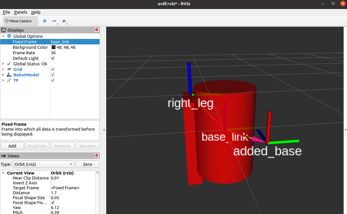
and you'll get something similar to this, enabling the TFs:

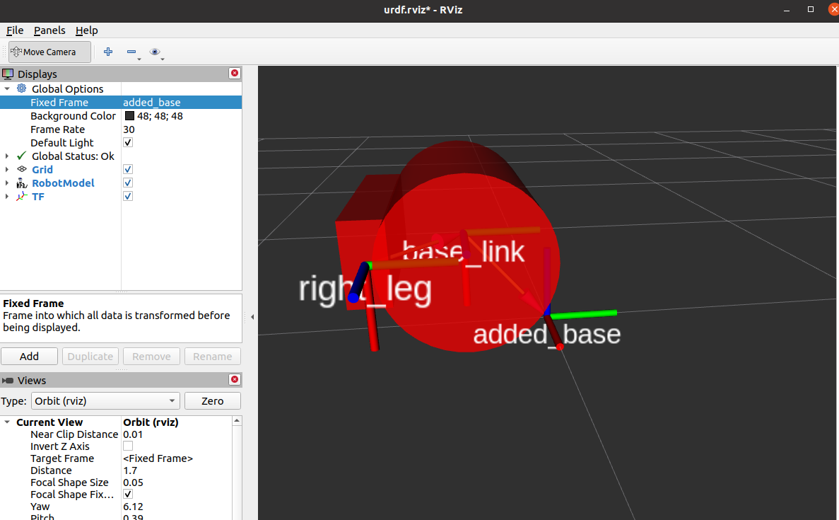
The new link appear! But the point of view did not changed, as base_link is still the fixed frame for rviz. Change the fixed frame to the new added_base and you'll get something like this:

In your specific example, you'll have to add a base_link as the parent of base_link_chassis.


