I have been using the FreeIMU library successfully but now I want to add an external magnetometer that I can mount away from my motors.
I've figured out how to modify the FreeIMU library to use an external magnetometer and I am getting data.
What I can't figure out is what I need to change now that my magnetometer orientation has changed.
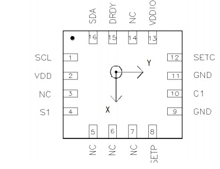
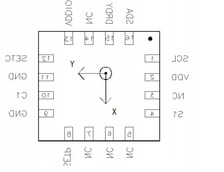
On the free IMU it is mounted like this

The external compass is mounted like this - upside down - rotated 180° around x

I am changing the value inside the
void HMC58X3::getRaw(int16_t *x,int16_t *y,int16_t *z)
{
    *x = cache_x;
    *y = cache_y;
    *z = cache_z;
}
function as all the other code calls this to get the magnetometer data.
So far I have tried:
Changing the sign for the y and z values after I have got them from the magnetometer.
Changing the sign for the y value only
Changing the sign for the z value only
Added 180 to both the y and z values
Subtracting 180 from both the y and z values
Subtracting 180 from y and adding 180 to Z
Adding 180 to y and subtracting 180 from z
Changing nothing
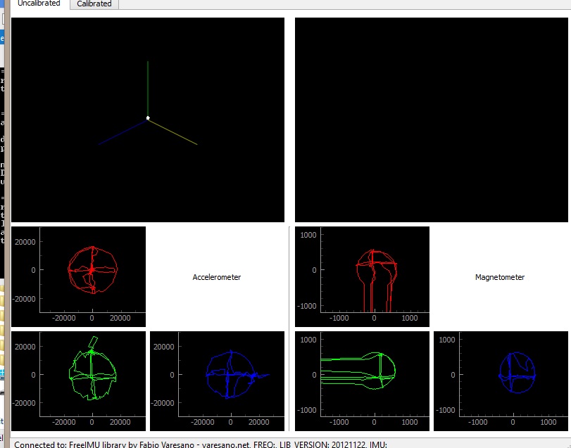
The calibration GUI gives always gives me strange results, and doing the changes above just rotated/mirrored the magnetometer red and green graphs. I am unable to get rid of the key hole shape.

The red is XY. The green YZ. The blue is ZX. Does the fact that ZX works mean that my issue is with the Y value?
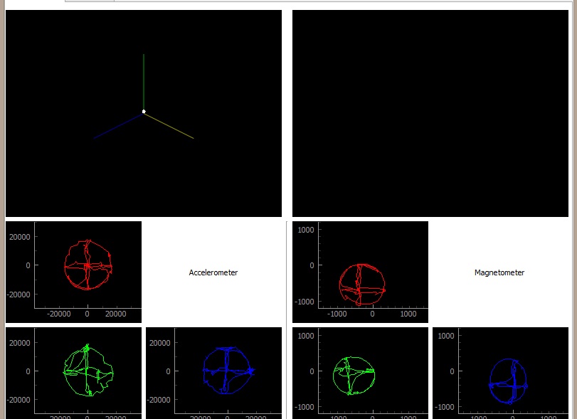
This is how it looks using the on board magnetometer.

What should I try next?
Thanks Joe
EDIT
I tried rotating the external magnetometer so it is in the same orientation as the FreeIMU magnetometer and I still get the same result so I don't think its the difference in orientation that is causing the problem.
So then I thought maybe its because the FreeIMU is mounted central to the rotation axis and the external magnetometer is mounted about 20cm above. I tested this by rotating only the external magnetometer around itself and I still got the same result.
This is all seems strange, do you think its possible that the external magnetometer I have brought is faulty? Any way to confirm it is working properly on its own?
Thanks
EDIT
Managed to get circles plotting by changing the gain from 0 to 1. It seem my new magnetometer was being saturated.
Now I just need to work out how to change my values around so the orientation is correct.