3
$\begingroup$

I am fairly new to the DH-transformation and I have difficulties to understand how it works. Why are not all coordinates (X+Y+Z) incorporated into the parameters? It seems to me that at least one information is useless/goes to the trash, since there is only a, d (translatory information) and alpha, theta(rotatory information).

Example: The transition between two coordinate systems with identical orientation(alpha=0, theta=0) but with different coordinates(x1!=x2, y1!=y2, z1!=z2). DH only makes use of a maximum of two of these information.

Please enlighten me!

Greetings

:EDIT:

To clarify which part of the DH-Transform I don't understand, here is an example.

Imagine a CNC-Mill(COS1) on a stand(COS0) without any variable length(=no motion) between COS0-COS1. For some reason I need to incorporate the transformation from COS0-COS1(=T0-1) into the forward transformation of my CNC-Mill. DH1

DH-Parameters for T0-1 would be a=5mm, alpha=90°, d=2mm and theta=90°. Assuming this is correct, the dX=10mm information is lost during this process? If I recreate the relation between COS0 and COS1 according to the DH-Parameters, I end up like this: DH2

As far as I understand, on non parallel axis the information is not lost because the measurement of a/d would be diagonal, therefore include either dX/dY, dX/dZ or dY/dZ(pythagorean theorem) in one parameter.

Where is the flaw in my logic?
$\endgroup$
6
  • $\begingroup$ What I see as the possible flaw here is the constraint "the Xn axis intersects both Zn-1 and Zn axes" (Via Wikipedia). If you rotation COS1 by 45 degrees, the issue would go away, and you would get an "a" parameter that is calculated from dZ and dX, it would be that 11.36mm value. $\endgroup$
    – Matt Brown
    Commented Jun 29, 2015 at 15:13
  • $\begingroup$ Yes, that was my point in the last sentence of my edit. But I don't know of any rule which I might have broken in DH terms. $\endgroup$
    – dcpria
    Commented Jun 29, 2015 at 15:49
  • $\begingroup$ It appears that the rule you have broken is that rule I quoted. In your current setup (figure 1), the X axis in COS1 does not intersect Z in COS0. Your figure 2 shows that you ended up forced into this constraint. $\endgroup$
    – Matt Brown
    Commented Jun 29, 2015 at 16:07
  • $\begingroup$ I am not sure if I understand you correct. The Wikipedia page says: "2. the x-axis is parallel to the common normal". Which means there are only two ways to set it, facing away/towards the previous COS. If I would want it to intersect, i would need to rotate COS1 by 45° (as you mentioned), but this would result into a wrong z-axis of COS1(if it would be a motion axis). $\endgroup$
    – dcpria
    Commented Jun 29, 2015 at 17:33
  • $\begingroup$ Okay, now I understand the point you have made and I can see the flaw in my logic. DH doesn't necessarily place the the coordinate systems into the actual physical axis (like in the video mentioned, posted by @Chuck around 0:56)the origin is not in the center of the actuator. So the dX information actually is not taken into account, but will be with the next transform(T1-2). So a way to cope with this for programmatically visualizations seems to be to insert another COS between COS0 and COS1, which is rotated by 45°. $\endgroup$
    – dcpria
    Commented Jun 29, 2015 at 18:37

4 Answers 4

3
$\begingroup$

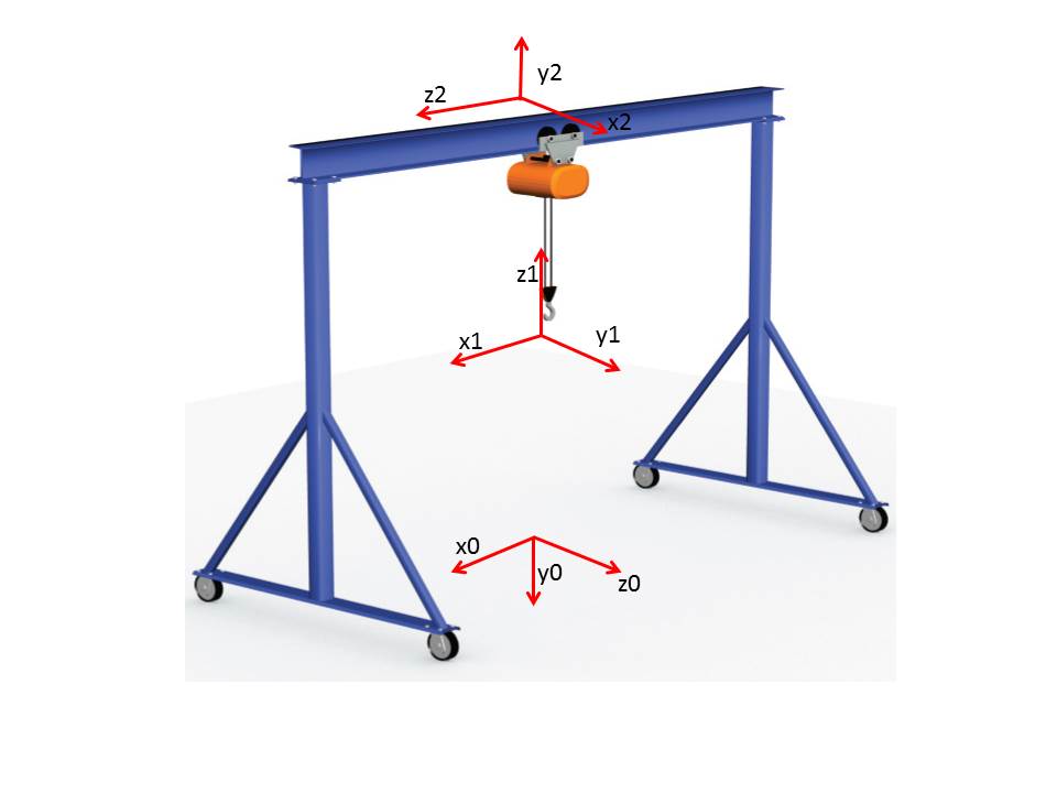
In DH, the Z axis always goes along the direction of variability. For a rotational (revolute) joint, that means Z is the axis of rotation. For a translational joint (prismatic) the Z axis is in the direction that the joint can translate. For each direction the robot can be actuated, a coordinate system is needed. So your example of a gantry crane, if that crane can be actuated in 3 directions, then it will take 3 coordinate systems to define said crane. Then the CNC mill will need 3 as well.

So, now taking a step back. Since our hypothetical 3D gantry crane has 3 coordinate systems, and in each coordinate system the Z axis is along the direction of freedom, you can imagine that from a global perspective, X,Y and Z are dealt with.

I made a quick illustration. If you look, you can see that Z2 defines a direction that the crane can be actuated, but it is in X direction of the preceding coordinate system (X1). Z1 also defines a direction of acutation, but it is in the Y direction of the preceding coordinate system (Y0). So from a global perspective, the X,Y,Z are essentially incorporated.

So the basis of your question boils down to, "why is only Z used as the axis of actuation?" I don't have an answer for that, other than probably the math would break down somewhere.

enter image description here

EDIT

More info based on updated description. To transform between two coordinate systems with no variability in between them, all that is required is a homogeneous transform, as shown. Reference for how these matrices are formed can be found here on page 65 of the text.

enter image description here

$\endgroup$
1
  • $\begingroup$ Sorry, if I didn't express my question clear enough. Please see the edit of my original post. $\endgroup$
    – dcpria
    Commented Jun 29, 2015 at 13:22
2
$\begingroup$

You don't need an explicit declaration for X, Y, and Z because the information is all relative to the previous joint.

For a terrific tutorial, see this video.

You don't typically use DH parameters to generate a transform from one fixed coordinate to another fixed coordinate; you use them to define joint motions.

In your example, you want to recreate the transform from COS0 to COS1. (By the way, cos is the symbol for cosine I would suggest using F for denoting different frames of reference) You use the following DH parameters:

d = 2mm

$\theta$ = 90 degrees ($\frac{\pi}{2}$)

r = 5mm

$\alpha$ = -90 degrees ($-\frac{\pi}{2}$)

The problem here is that, again, DH parameters are for joint motion, not for fixed locations, so all you are doing is defining the location and orientation of the Z-axis. In DH parameters, the Z-axis is the axis of motion. As mentioned about 1 minute into the video I linked, "DH parameters are only concerned with the motion of the links, not the physical placement of components."

You are attempting to use DH parameters to locate a physical position where DH parameters are used to define an axis of motion.

Your confusion comes from the fact that you are misusing the DH parameters.

$\endgroup$
4
  • $\begingroup$ Thanks, this video explains it quite well, though I can't get my head around that special case explained in original post. It seems to me that DH is not applicable for two coordinate systems with all 3 axes parallel. Instead I would need redefine the orientation of the second coordinate system (e.g.: like at 2:36 in the video). Resulting in that only one axis can be parallel in both systems. Is this correct? If it is, how does this work in practice when both systems have all 3 parallel axes? (e.g. a CNC-Mill on a gantry crane. Yes, it's ridiculous but easy to visualize. ) $\endgroup$
    – dcpria
    Commented Jun 24, 2015 at 18:29
  • $\begingroup$ @dcpria - I added a bit more to my answer in hopes of clarifying for you. $\endgroup$
    – Chuck
    Commented Jun 24, 2015 at 18:58
  • $\begingroup$ I have added an example to clarify my question. I see how the global X,Y,Z information incorporates each axis motions, my question is about the X,Y,Z information within one transform between two coordinate systems. $\endgroup$
    – dcpria
    Commented Jun 29, 2015 at 13:14
  • 1
    $\begingroup$ @dcpria - DH parameters are not intended to locate physical objects, they are used to define motions. This is your confusion. See an expanded explanation in my edited answer above. $\endgroup$
    – Chuck
    Commented Jun 29, 2015 at 18:26
1
$\begingroup$

To be short and simple, D-H notation uses third axis as the reference to the other 2 through out the calculations.

$\endgroup$
1
$\begingroup$

I studied DH transformation for industrial robotics exam. In DH procedure you consider only 1DOF joint (eventually decomposing a xDOF joint in x 1DOF with 0 link length) and you set relative z-axis parallel to joint axis and x-axis perpendicular to the plan defined by k-joint axis and k+1-joint axis. In this way you can consider every joint-to-joint transformation as a spin on relative z-axis and a spin on x-axis (the spin is defined as rotation and translation on the same axis and is the only 3D commutative tranformation).

So, for each joint you get a transformation matrix that depends on joint variable (rotation or translation on relative z-axis) and on link length and geometry(rotation and/or translation on relative x-axis) .

The total transformation matrix is the product of all single joint transformation matrix and it depends on all joint variables and on robot geometry

I hope that this fast explanation is helpful and I hope that I did not made too many grammatical mistakes!

EDIT

DH transform is normally used to compute kinematics in robotic arms and it doesn't work for all kind of motion. In some cases it needs a "patch" in order to be usable for some configuration (i.e. adding an auxiliary 0DOF link to include some geometries). In your case I think you should decompose your sistem in two different transformation T0-1 and T1-2 to include every translation. In alternative you can set x-axis parallel to diagonal in order to have only one transformation matrix T0-1

$\endgroup$
1
  • $\begingroup$ Thanks, I understand the "idea" behind the DH-transform, my questions is rather more about transform between two coordinate systems. I have added an example to my original post to clarify it. $\endgroup$
    – dcpria
    Commented Jun 29, 2015 at 13:20

Your Answer

By clicking “Post Your Answer”, you agree to our terms of service and acknowledge you have read our privacy policy.

Not the answer you're looking for? Browse other questions tagged or ask your own question.