2
$\begingroup$

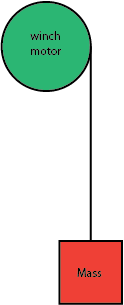
I'm having trouble with a gear motor being powered by a power supply, while it is being driven by the load in the same direction as the driver wants to drive it. Here is a simple diagram:

enter image description here

The gear motor is the prime mover in a winch system that lifts and lowers a mass of about 25 pounds.

for reference this is the motor:

https://www.superdroidrobots.com/shop/item.aspx/ig52-04-24vdc-082-rpm-gear-motor-with-encoder/1181/

This is the motor driver:

https://www.basicmicro.com/RoboClaw-2x15A-Motor-Controller_p_10.html

And this is the power supply:

https://www.amazon.com/gp/product/B07ML2MP9Q/ref=ppx_yo_dt_b_asin_title_o00_s00?ie=UTF8&psc=1

I'm controlling the system by doing all speed/position control on a raspberry pi, sending forward/backward duty cycle commands to the roboclaw over serial. When lifting the system performs exactly as expected: the motor smoothly rotates. Initially, when lowering, if I sent the motor driver a duty cycle to lower it would jerk, then freewheel, then lower very slowly, and that channel of the driver would no longer function, and would produce a 'damaged' error code. I solved this by simply sending it a duty cycle of 0 and allowing it to lower slowly. This is turning out to be inconvenient for my project timeline, so I'm trying to solve it. I found this video:

https://www.youtube.com/watch?v=-5YFYhBU-jQ

So I'm guessing the H bridge on the driver opening up when lowering, allowed the motor to try to sink current into the power supply, the power supply didn't like that and would get fussy and temporarily shut off, thereby shutting off the motor driver, but then the motor driver would get powered on by the back drive voltage of the motor, freak out, freewheel, get damaged, and shut everything down. This was somewhat confirmed by added a forward bias schottky diode to the positive pole of the power supply, as I can now give the system a lowering duty cycle and it will run without destroying itself. HOWEVER now when it is lowering, the behavior is very jerky, like the driving of the motor is producing a current that want's to run into the power supply, but it has nowhere to go. The shuddering vibration is not great for the mechanical aspects of the system, so I'd like to try and solve this. Is there anything I can add to the circuit to help smooth out this behavior? or anything I can add to give the driven motor current somewhere to go?
$\endgroup$

1 Answer 1

2
$\begingroup$

What you need is something that is generally referred to as a "brake resistor."

It looks like there's an application note specifically for your product. It says, in part:

A voltage clamp is a circuit used with a motor controller to divert excess energy away from the control circuitry and power supply to prevent damage. In the two applications discussed below a MOSFET is used as switch to divert excess power through a power resistor where it’s dissipated as a heat.

...

The primary purpose of a voltage clamp is to protect a motor controller’s power supply from the regenerative power created when a motor is stopped or slowed down quickly. A motor spins when power is applied to it however it also acts as a generator when slowing down or suddenly stooped. This energy opposes the flow of current to the motor and is directed back to the motor controller and power source. Switching power supplies are not designed to handle this power surge and some batteries will also not tolerate the sudden inrush of current. A voltage clamp detects this power surge as a rise in voltage and sends the excess current to a resistor where it’s turned in to heat.

Basically exactly as it says - you can generate power by back-driving a motor; this is how regenerative braking works. The catch is that there needs to be somewhere for the power to go, and switching power supplies can't put the power back in the battery.

The solution, then, is to just dump that excess power. Burn it off as heat. The easiest way to determine a power rating on your brake resistor would be to use your power electronics as a guide, with the assumption that your regenerative power generation capacity is going to be approximately the same as your applied power generation capacity.

That is, if you've got a system where you could provide 5 amps at 12 volts, then you can apply (5*12) = 60 watts of power. If you can provide 60 watts winching up, then the winched load could back-drive at 60 watts lowering.

The application note states:

Select the resistor for the voltage clamp based on the table below. Note that the Digikey parts listed below are all 50 watt resistors which are sufficient for most use cases. However if the voltage clamp is expected to be on for long periods of time or the motor is driving a large load a resistor with a higher power rating may be necessary.

This is the board manufacturer's suggestion, so you could start with this, but again I would (personally) look at your continuous power draw on the hoist operation and rate at 1.5 to 2x the power draw for the brake resistor's power rating.

As a final note - the manufacturer is suggesting you use FIFTY WATT power resistors. Imagine touching a 60 watt incandescent light bulb - the brake resistors are going to get about that hot. Don't put this near any wire harnesses, combustibles, etc. It's going to get very hot - the brake resistor alone is what's controlling your load's descent.

$\endgroup$
1
  • 1
    $\begingroup$ What a very detailed answer. I have yet to try this out, but considered it's from documentation, and explicitly concerning my application, I would say this problem is solved. Thank you! I can't believe I missed this in the documentation. $\endgroup$ Commented Sep 22, 2020 at 15:52

Your Answer

By clicking “Post Your Answer”, you agree to our terms of service and acknowledge you have read our privacy policy.

Not the answer you're looking for? Browse other questions tagged or ask your own question.