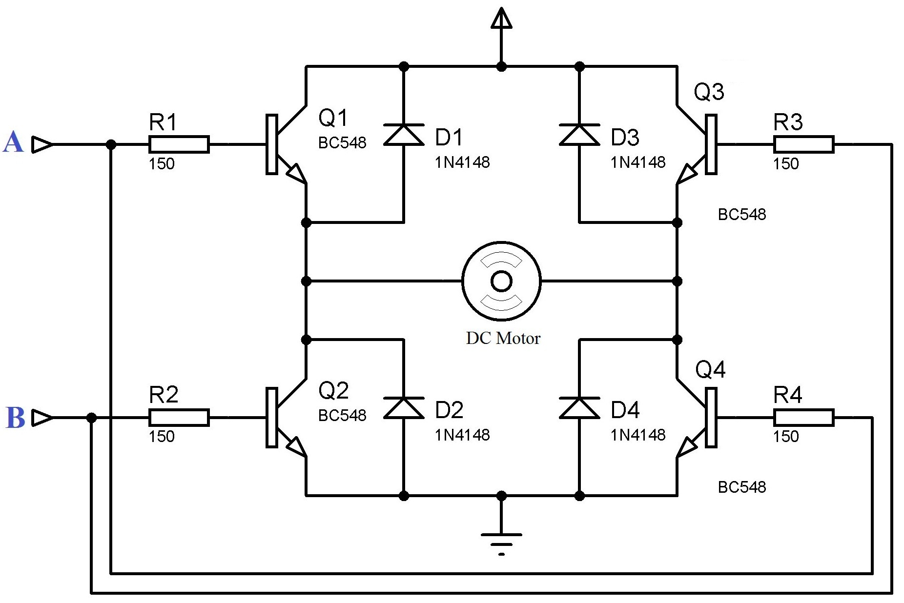
I am new to electronics.the question is buzzing in my head since i first saw the H bridge configuration.please answer the question briefly
3 Answers
Basically (in reality anything have a sligth aspeact of everything else, nothing is ideal) the DC motor is mainly inductance in serie with small resistance.
Your typical use is close Q2+Q3 and send PWM to Q1+Q4 (or vice versa).
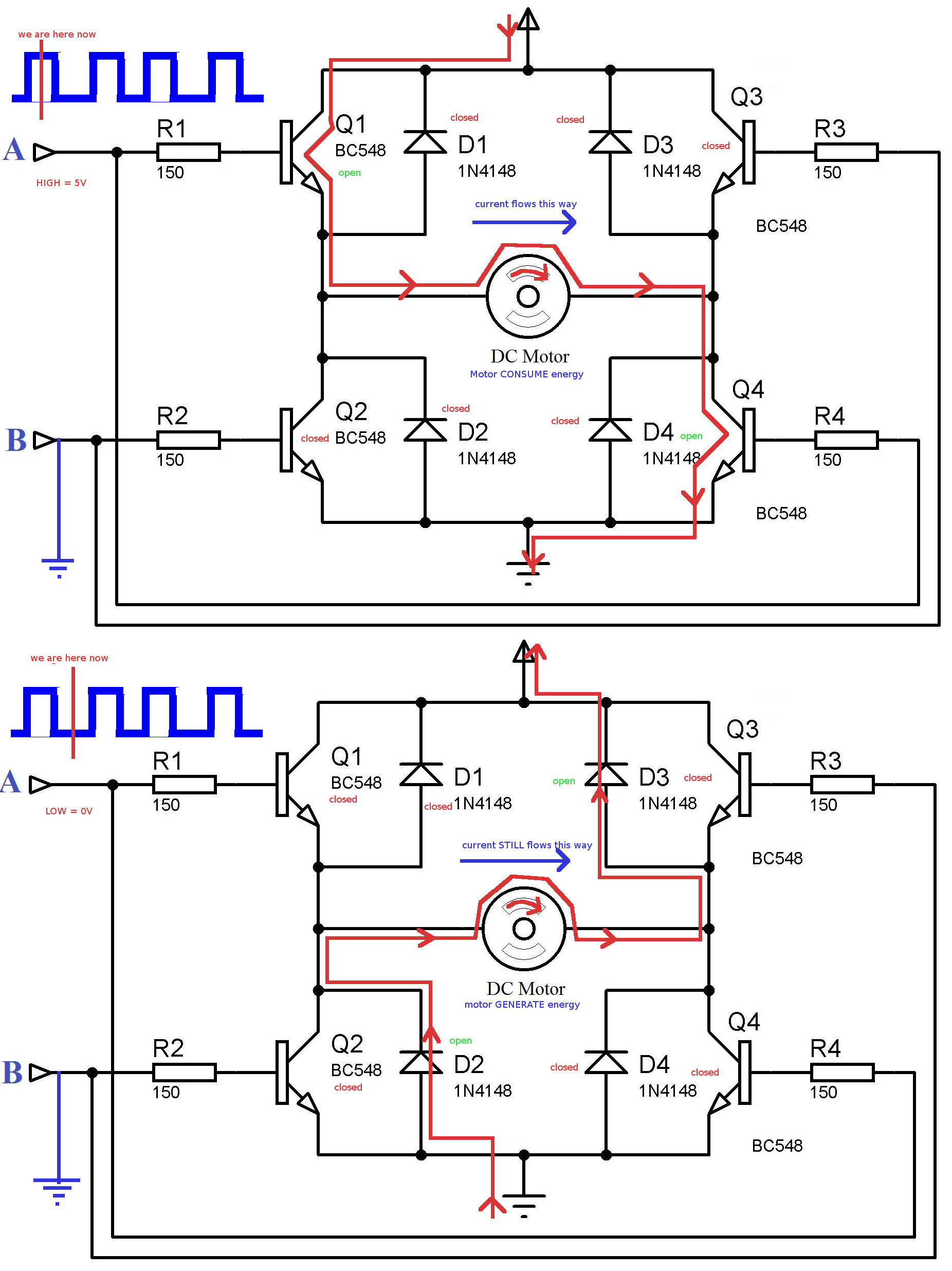
When PWN is on, Q1+Q4 are open and current goes to DC motor from left to rigth. It start to rotate (or increase rotation when rotating) (slowly as incductace resist change of current, mechanical inertia also works against change). Nothing fancy here. Current goes PWR-Q1-DC-Q4-GND
Then the PWM goes down, Q1+Q4 closes, but morot is rotating (mechanical inertia) and its inductance tries to force current thru from left to right. At the moment it behave as dynamo (or a battery) and voltage goes so high so to force the current of the same value and direction.
And now the diodes kick in. On DC there is - on the left and + on the right (as on baterry forcing the current the same way) and when it reach some limit D2 opens (as there is minus under GND 0 V voltage on the DC left) and the D3 opens (as there is voltage higher than PWR on DC right) and the current flows thru DC in the same way back to main battery. GND-D2-DC-D3-PWR.
But the DC (and everything else) have some resistance, which burns the energy and its inductance have only limited capacity (even if enforced by mechanical inertia of rotating motor) so the current goes slowly down (and will stop eventually as the DC motor would slower so much, that there would be not enought voltage to open diodes and overcome main battery at the same time).
But your PWM goes up again much sooner thant this stop happens, so the DC just slows a little and those Q1 and Q4 opens and main battery suplies current again which forces the DC to rotate faster.
The rate (speed) of PWM is so fast, that mechanical inertia makes that invisible and only statistical difference matters here.
Dependind on the time the PWM is on(up) and time it is off(down) the DC motor have just part of the maximal possible power and so its rotation is slower then maximal possible. As on open Q1+Q4 there is full current from battery it have much better force to move, than if you limit the current with eq. resistor. (if goes full strenght for moment, then no strenght at all instead of going only half streng all the time - so it is able to overcome more resist of environment, even if it is not able to rotate fast)

-
$\begingroup$ gilhad, can you please draw the direction in the given figure???It would be very helpful to me if you do so.... $\endgroup$ Commented Mar 31, 2017 at 10:42
-
$\begingroup$ I added picture - notice, that the PWM is usually like 1kHz, that means switching from low to high and back 1.000x per second. Mechanical motor reacts much slower, so it keeps rotating even if not powered for a split of second. And the inductance keeps the current flowing the same way (for a moment) so it generates eve higher voltage, than was supplied by battery and the current flows from high side INTO battery BACK. $\endgroup$– gilhadCommented Mar 31, 2017 at 14:39
-
$\begingroup$ If you want to rotate motor in reverse direction, you just keep A input low and put PWM on B input. Q1 and Q3 switch roles, as wel Q2 and Q4. And everything is mirrored. (Notice also, that in reality you need the A/B inputs as high as main power to be able to open Q1/Q3, so real H-bridges are littlemore complicated to be able to work reliably, but idea is the same) $\endgroup$– gilhadCommented Mar 31, 2017 at 14:42
-
$\begingroup$ So you can mark this as solution and vote me up :) $\endgroup$– gilhadCommented Mar 31, 2017 at 23:31
-
$\begingroup$ How can I contact with you..if I have another problem??? $\endgroup$ Commented Apr 2, 2017 at 4:28
keep it simple:
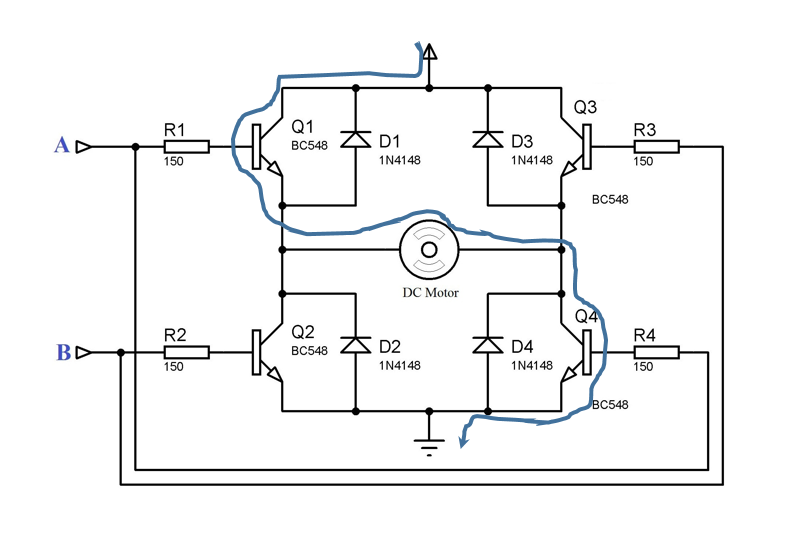
when A is H-Level and B L-Level then Q1 and Q4 are in the saturation region so the current flows in the direction as follow:
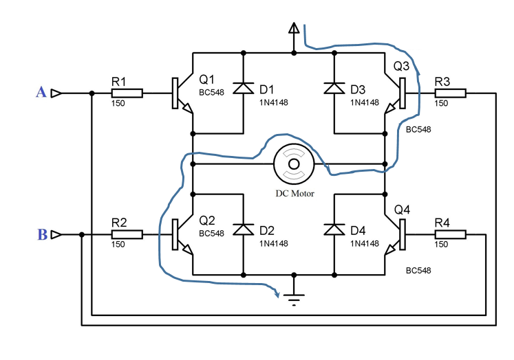
on the other option: A is L-Level and B H-Level
the rest of the options: A=B= H-Level or A=B= L-Level are not going to move the motor
-
$\begingroup$ Does not address the diodes in question at all $\endgroup$– gilhadCommented Mar 31, 2017 at 9:15
-
$\begingroup$ xoce...I asked the direction of current following through the diodes...not through the transistors..I think you understand my question.. $\endgroup$ Commented Mar 31, 2017 at 11:00
q1 and q3 will never really turn on if the voltage applied to A or B is less than the motor supply voltage, NPN transistors require that the base voltage is greater than the emitter voltage by 0.6v, lets say without the motor running its emitter is sitting at a random value of 2v, when you apply say a 5v signal to it, the emitter will then only every rise to 4.4v
if motor supply is 12v then A or B will have to reach 12.6v to turn on q1 or q3, this is why q1 and q3 are usually pnp transistors. q1 and q3 are forming emitter followers(?) and its not a great way to use them in a circuit like this. I'd also change the diodes to 1n4001 or 1n4007

