0
$\begingroup$

Let's say I have a robot with few sensors and dif. drive. And I want to perform sensor fusion using UKF.

Dif. drive can take commands, so my first thought was to use command (linear and angular speed) as filter's "control command". By "command" here I mean something that I send to dif. drive to make it move, like they do in ROS teleop utility. It means that when I run prediction, I use these parameters. But then I found few publications, like this: https://nitinjsanket.github.io/tutorials/attitudeest/kf

It merges gyro and accelerometer, and it runs "predict" every time gyro data received, and "update" every time accelerometer data received.

Which is understandable: they have gyro and they want accelerometer to comply (am I correct?) It can be done in case there is no "control command". But what if I have it? What if I have few sensors and "command"?

Even more, what if I have few sensors each of them can be used as input, for example, two different gyroscopes?

So my question is, are there any rules to choose what is used during "predict" and what - during "update"? And does it mater?

Second question: in Complimentary filter, I can choose alpha, so that accelerometer is, say, 1% and gyro 99%. How can I do it in UKF? I don't think that I can alter values in Q or P matrices, because a) they are related to properties of sensors and b) it makes no sense. Say, gyro has sigma 0.01 and accelerometer 0.01, yet one will drift, so sigma should grow?

As you can see, I am pretty much lost here, so any pointers are greatly appreciated. The objective is to use UKF to merge GPS/accel/gyro/magnetometer/... in a way that makes me understand what and why I am doing.

Thanks :)

$\endgroup$
1
  • $\begingroup$ While your questions are valid - from what I can see - it's not clearly structured. Could you re-write your questions in a more readable fashion? $\endgroup$
    – Scoeerg
    Commented Jun 28 at 14:20

1 Answer 1

1
$\begingroup$

First of all, usually the "command" to give to any robot is a publisher geometry_msgs/msg/Twist

geometry_msgs/Vector3 linear
geometry_msgs/Vector3 angular

OR geometry_msgs/msg/TwistStamped

std_msgs/msg/Header header
geometry_msgs/msg/Twist twist

which essentially tells to robot to follow a reference velocity in all 6 degrees of freedom:

$\vec{v}_{linear} = \left(\dot{x}~\dot{y}~\dot{z} \right)^T$ $\vec{v}_{angular} = \left(\dot{roll}~\dot{pitch}~\dot{yaw} \right)^T$

any rigid body has. The ROS teleop keyboard for example publishes Twist-Messages. Convention(!) is the topic name cmd_vel for this Twist or StampedTwist message.

Now of course, you need to understand this is the reference(!) to a low-level controller, which will try and follow this reference velocity. So, the actual robot might move differently (due to control errors or kinematic constraints, especially non-holonomic constraints).

What is usually fancifully called Sensor Fusion is a simple State Observer of which there are a couple of well-known ones: The Luenberger/State Observer which is described in the linked Wiki above, and three Kalman Filter:

Standard Kalman
Extended Kalman (EKF)
Un-Scented Kalman (UKF)

which essentially all work by correcting prediction error. The scope of the answer is too small to go into details, but I invite you to read about those concepts in the provided links, as they will clear things up.

Now this is a scheme of any observer.
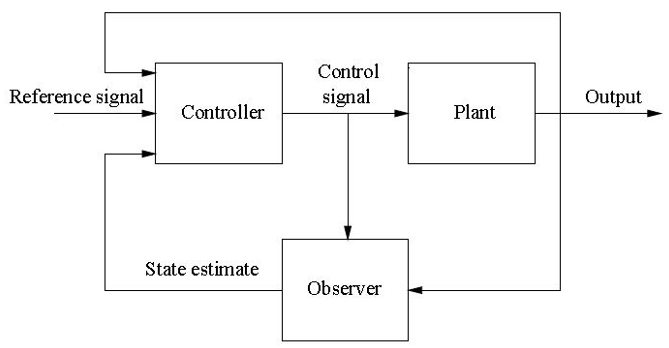
Observer Scheme

Here's a translation in "Robotic Terms":

Plant = Robot
Reference Signal = Twist/StampedTwist
Controller = Low-Level Controller
Output = Sensor Data (Gyro, IMU etc.)
Observer = Observer (Kalman, Luenberger etc.)

The output of your Observer is the State Estimate - which usually for robots means the estimated current position and velocity (relative to a fixed frame - usually called odom).

I sincerely hope this clears it all up. And here's what it looks like "inside" the Kalman Filter:
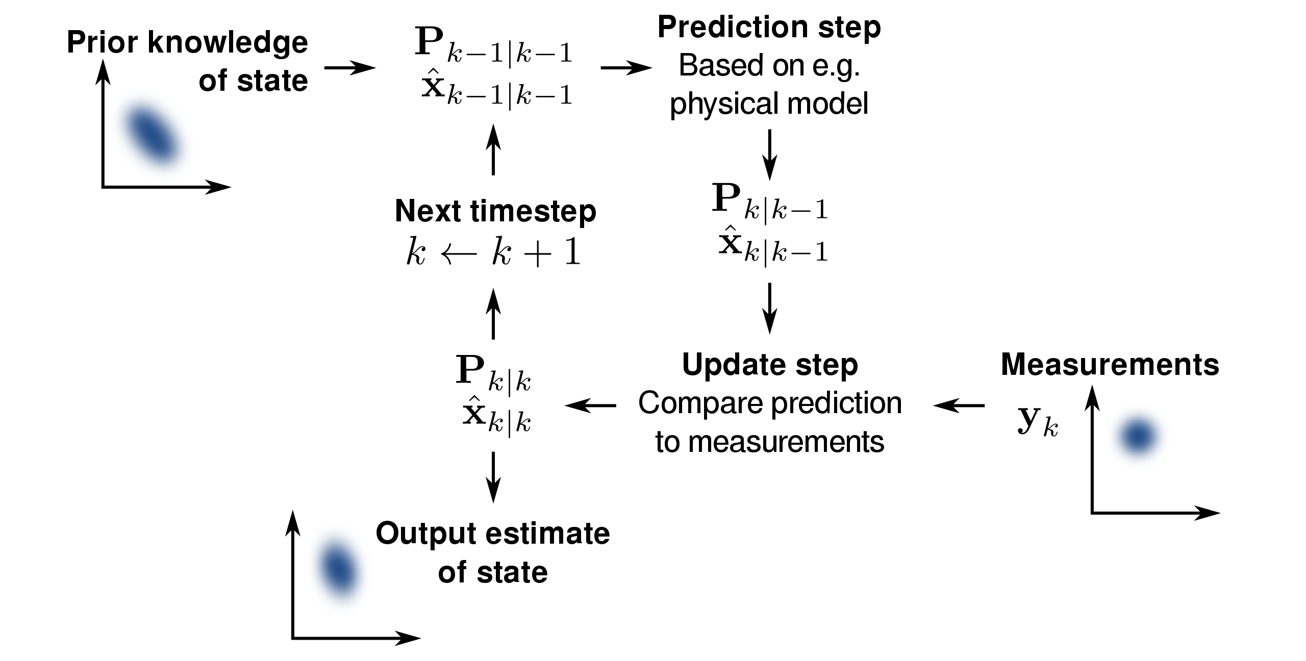
enter image description here

which - again - minimizes prediction error by correcting iteratively.

Let me try and answer some of your sub-questions:

they have gyro and they want accelerometer to comply (am I correct?) It can be done in case there is no "control command". But what if I have it? What if I have few sensors and "command"?

usually you can set a bool whether the Observer should use command or only sensor data to estimate states.

Even more, what if I have few sensors each of them can be used as input, for example, two different gyroscopes?

Standard Filters as used in localization package can fuse as many IMUs etc as you want. You only have to comply to localization package message type.

Second question: in Complimentary filter, I can choose alpha, so that accelerometer is, say, 1% and gyro 99%. How can I do it in UKF? I don't think that I can alter values in Q or P matrices, because a) they are related to properties of sensors and b) it makes no sense. Say, gyro has sigma 0.01 and accelerometer 0.01, yet one will drift, so sigma should grow?

I think(!) what you are asking is how to (fine) tune Kalman-Filters. You can set the process and (I think) sensor noise inside the parameters of the Observers as Covariance-Matrices. BUT(!) it's advised to do this carefully - it's not an easy task and standard-values are usually pretty good. This being said, the Covariance-Matrices (your "sigma") are updated periodically within the Kalman-Filter as it works - so they can and will drift.

$\endgroup$
15
  • $\begingroup$ Thank you. But my question was about a slightly different thing: I treated Kalman filter's input exactly as you described, and then I found an article (few of them, one link is above) that passed one sensor as an input (before predict) and another one before update. $\endgroup$ Commented Jun 29 at 19:55
  • 1
    $\begingroup$ The link to the article is in my post, above. $\endgroup$ Commented Jun 29 at 20:20
  • 1
    $\begingroup$ > This is the verbose parameter-file of the (E)KF. There is a misunderstanding. I am writing my own filter. I know how to use ROS2 Nav2, but I want to replicate the functionality myself, as I am learning the thing. $\endgroup$ Commented Jun 29 at 20:28
  • 1
    $\begingroup$ From a brief read, I believe the confusion comes from the article. It describes the Sensor (IMU) as the system "we would like to estimate the attitude [states] of the IMU" and the Gyro and IMU output as sensor data. The article treats the IMU as the system where the output is Gyro and IMU data (sensors). The localization package on the other hand wants to find the position, velocity and acceleration of a rigid body in space. $\endgroup$
    – Scoeerg
    Commented Jun 29 at 20:30
  • 1
    $\begingroup$ A Gyro has a dynamic (its behaviour is governed by a difference/differential equation). Hence you can treat it like any system (see Fig. in my answer and substitute plan for gyro) and the IMU as sensor producing (sensor) output for the plan (that is the gyro). Then the rest of my answer stands and is coherent with the article you read. $\endgroup$
    – Scoeerg
    Commented Jun 30 at 18:18

Your Answer

By clicking “Post Your Answer”, you agree to our terms of service and acknowledge you have read our privacy policy.

Not the answer you're looking for? Browse other questions tagged or ask your own question.