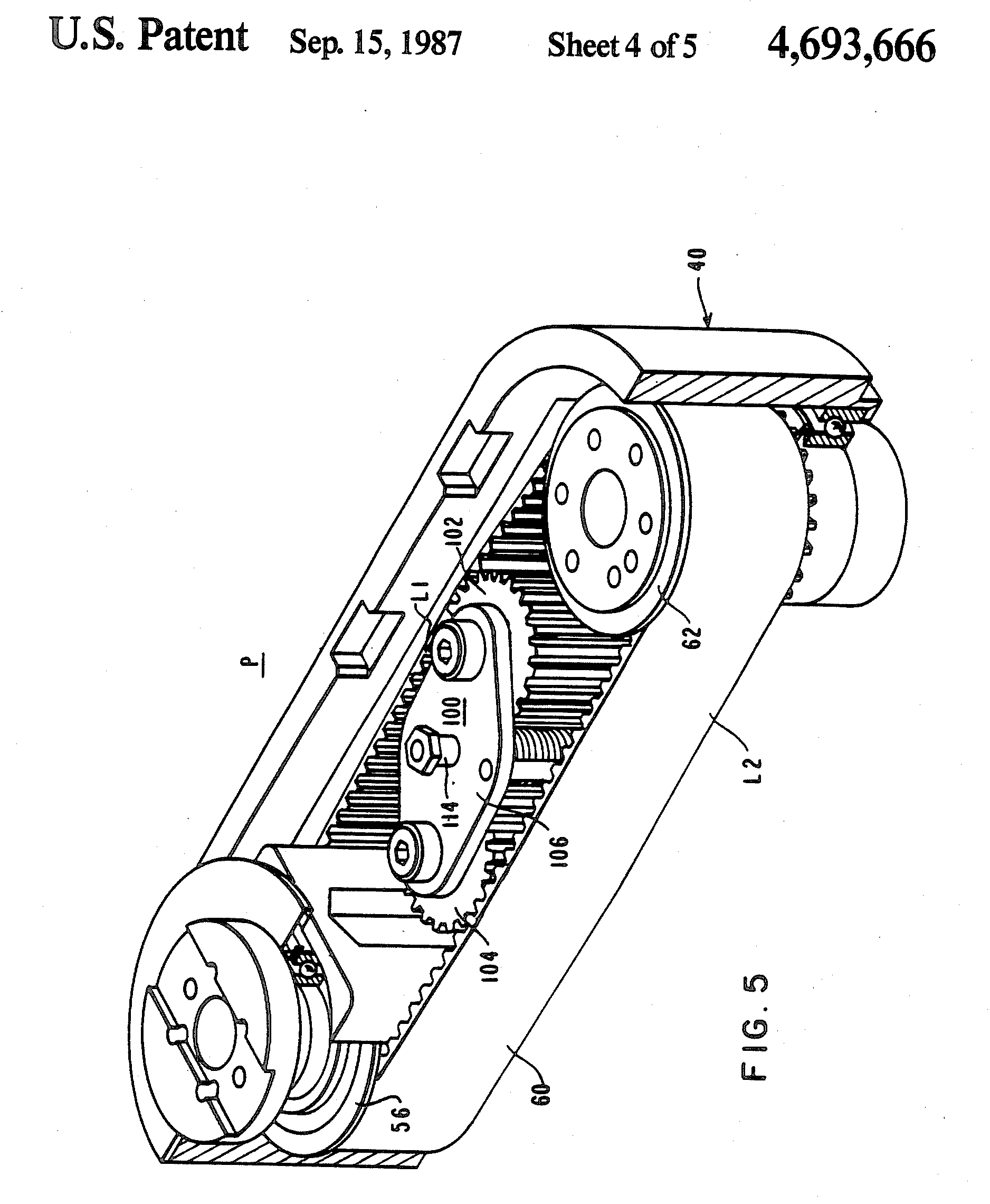
I found this drawing on google photos:
I don't understand why he used this part.
- Is it for reduction?
- What is its equation?
One of the problems with a belt driven SCARA system like this is that as the belts age, they stretch, so every belt should have a tensioner.
If you look carefully, it is clear that plate 106 rotates around shaft 114, and you can see the spring which provides the tension below it. Cogs 102 and 104 are free running. When the belt is new, plate 106 will be pushed close to the position shown. As the belt ages, the force of the spring will rotate plate 106 anti-clockwise, maintaining the tension of the belt.
This design cleverly tensions both straight sections of belt at the same time, by the same amount, and with the same pressure. This should make the system less susceptible to problems with unidirectional repeatability (moving from -90 to 0 resulting in a different position than moving from 90 to 0 for instance).
The circled assembly is a bi-directional tensioner which maintains the tension in the drive belt at a pre-determined level as the belt ages and stretches. The detailed description of the function of the assembly is explained in the original patent document (US Patent 4,693,666), available on Google patents:
The bidirectional tensioning for the belt 60 ... as shown in FIG 5, is achieved by the bidirectional belt tensioning and idler device 100 positioned within the belt loop and intermediate the toothed gears 56 and 62.
The device 100 includes rotatable toothed rollers, or pulleys, 102 and 104 for internal engagement with opposite lengths L1 and L2 of the belt 60 which are moving in opposite directions. The rollers 102 and 104 are connected by a yoke 106 which connects the supporting axes of the rollers. The device 100 is rotated about a torquing arrangement 110 which extends through a mounting plate 112. The torquing arrangement 110 includes an adjustable tensioning element 114 for rotating the 100 relative to the belt 60 to establish the desired tensioning of the belt 60.
Once the proper tensioning is established, the device 100 is secured by the fasteners. The desired belt tension corresponds to a predetermined torque associated with the tensioning element 114 and thus the belt 60 can be pretensioned via the tensioning device 114 without requiring visual access to the interior of the primary arm assembly P.
I've included the original diagram below for ease of reference:

When modelling the SCARA robot, this assembly should not need to be modelled with a separate equation. The function of the unit is simply to ensure that the drive assembly performs as expected, so you do not need to modify the equations for the drive assembly to account for the drive belt ageing and stretching over time.