2
$\begingroup$

I have a 3d physics simulation where I use a PID controller to reach a set orientation (orientation error drives a torque output). Which works well enough some cases, but in others it's not working as nicely as I would like - especially in the case of rapid rotation. I am still tuning however.

I'm not proficient in control theory, but I was thinking maybe perhaps that the controller is only ensuring the desired orientation is reached as a constraint, but not what the angular velocity should be when it gets there - ideally zero in most situations.

So I was wondering if it made sense to somehow combine a second PID controller that uses angular velocity rather than orientation mismatch as the error. I'm not sure if this makes sense, and if so if it should just output another torque that is summed with the torque of the other PID? Or if it's more complicated than that? Or if it would be duplicating the work of the first PID anyway?

I think I would want the angular velocity closer to zero, the more closer the orientation error is to zero - so I am not sure if any kind of scaling to do that makes sense? I can imagine that would then become a balancing act between the two PID's coefficients to determine how fast it can correct vs stability when stopping (But then that kind of sounds like what the first PID would be doing anyway!?).

Also in general I am not sure of the correct way to combine multiple PID controllers that are trying to balance concerns like that.
$\endgroup$
9
  • $\begingroup$ If it works well for small changes in setpoint, but not for large ones, you're probably experiencing integrator windup, or you need to limit velocity in a nonlinear fashion, beyond the natural velocity limit provided by the differential action of a PID. When does it behave well, and when does it misbehave? $\endgroup$
    – TimWescott
    Commented Dec 29, 2020 at 19:21
  • $\begingroup$ One of my worst cases involves user mouse input into the physics simulation to set orientation - which can be rapidly changing direction by design and builds up quickly to spiral out of control. At the moment that is using PD but not the I term. $\endgroup$
    – iam
    Commented Dec 30, 2020 at 4:01
  • $\begingroup$ Is the mouse movement forcing a rotation, or is it just changing the setpoint? $\endgroup$
    – TimWescott
    Commented Dec 30, 2020 at 4:56
  • $\begingroup$ The mouse movement case sets target orientation based off the current heading (I have both quaternion and euler variants). Then a PD is used to output torque that is applied to a rigid body in the sim. Because you can flick the mouse to rapidly to reorientate it can cause the spiral out of control issues. It could well be the case that I simply need to spend more time tuning the PID! But from the info given so far it also seems that it could make sense to perhaps interpolate the PID coefficients depending on angular velocity or try something like P x positionError + D x angularVelocityError $\endgroup$
    – iam
    Commented Dec 30, 2020 at 6:54
  • $\begingroup$ Your comment on limiting velocity in a nonlinear fashion is interesting too. I am not sure if that means it can sometimes be helpful to introduce a squared or more term to make the PID a polynomial? I imagine going past a 2nd or 3rd power would rapidly get squiggly and uncontrollable. Sorry if my understanding is a bit strange as I am coming from a software simulation perspective without a background in control theory $\endgroup$
    – iam
    Commented Dec 30, 2020 at 6:58

1 Answer 1

6
$\begingroup$

Find here a similar question.

A well-tuned position PID is most of the time capable of accomplishing the task of reaching a target with zero velocity. The central point here is that you shall provide the PID with a smooth reference trajectory (planning or input-shaping) connecting your starting point with the desired orientation.

Usually, this reference trajectory is generated in the form of a minimum-jerk path that reduces oscillations, especially at the onset and the endpoint. To code this trajectory you ought to resort to a 5th order polynomial:

$$ r(t) = r_i + (r_d-r_i) \cdot \left( 10\left(\frac{t}{t_f}\right)^3 -15\left(\frac{t}{t_f}\right)^4 +6\left(\frac{t}{t_f}\right)^5\right), $$ where $t_f$ is the time to execute the whole trajectory, hence $t \in [0,t_f]$ and $r_i$ and $r_d$ are the starting and the ending points, respectively.

This smooth input will guarantee that the PID won't struggle to deliver its effort to reach the target at a very low speed without overshoot.

Of course, you are still required to properly tune the PID to let it behave successfully when fed with stepwise inputs.

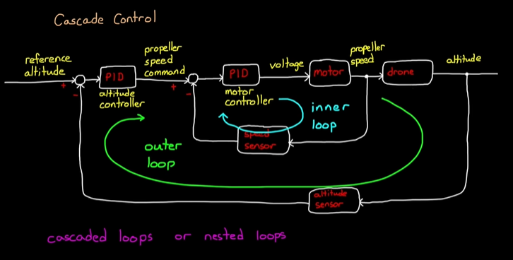
That said, adding cascaded PID controllers is also quite common. The diagram foresees that controllers are nested from the inner to the outer following this order:

  • inner: torque (current) PID
  • intermediate: velocity PID
  • outer: position PID

Have a look at this quite enlightening resource to see how this is done.

You could also have implementations with only 2 cascaded PID out of the 3 above (e.g. velocity and position) but always in the prescribed order.

The key point of cascaded PID controllers is that this design can improve the overall performance and allow for tuning according to this procedure:

  1. First tune the torque (current) inner PID considering the motor+load as the plant;
  2. Then, tune the velocity intermediate PID considering the motor+load+current_pid as the plant;
  3. Finally, tune the position outer PID considering the motor+load+current_pid+velocity_pid as the plant.

Thereby, at the end of the story, there will be only one objective that is the position setpoint. Still, a cascaded controller cannot impose velocity setpoints, for example; rather, it will serve "merely" to improve the closed-loop system performance.

Find below an illustrative example concerned with the altitude control of a drone where a 2-level cascaded PID controller is employed. The outer altitude (position) controller is combined along with the inner velocity controller.

cascaded PID

This example is taken from "Understanding PID Control, Part 7: Important PID Concepts" by Brian Douglas.

$\endgroup$
9
  • $\begingroup$ I'm struggling a bit on how to properly nest the PIDs even after looking at some diagrams online - I suspect it is something very simple that isn't clicking for me. For example I apply a torque to a rigid body in my sim. So currently I understand positionError => PID => Torque. To nest the velocity PID inside I am not sure what is the error I would feed it or what it should output? $\endgroup$
    – iam
    Commented Dec 29, 2020 at 17:39
  • 1
    $\begingroup$ I think I at least get your point on the minimum jerk path. As I believe I understand it effectively helps guide towards the right mathematical characteristics for zero velocity at the set point (orientation) - at the expense of a latency. One of my worst failure cases actually involves rapid user mouse input to orientate. So that is good for me to consider on how I may want to filter that. $\endgroup$
    – iam
    Commented Dec 29, 2020 at 17:55
  • 1
    $\begingroup$ For permanent-magnet DC brushed, brushless, or AC brushless motors, the inner loop would use motor current as a proxy for torque, and would control currentError -> PID -> current (and, hence, torque). Other motors would have other proxies for torque. The next loop out would control velocityError -> PID -> torqueCommand. The next loop out would control positionError -> PID -> velocityCommand. Note that you almost certainly don't need full PID controllers on the inner loops, and want to avoid the integral action unless a loop is far faster than the loop inside of which it is nested. $\endgroup$
    – TimWescott
    Commented Dec 29, 2020 at 19:18
  • $\begingroup$ TimWescott's comment is spot on! I've amended my answer a little further pointing out that cascaded PIDs cannot allow for multiple objectives but are used to get improved performance. $\endgroup$ Commented Dec 29, 2020 at 21:08
  • 1
    $\begingroup$ A note that this is a quite useful reference for people like me trying to understand the basic concepts: mathworks.com/videos/… $\endgroup$
    – iam
    Commented Dec 30, 2020 at 7:59

Your Answer

By clicking “Post Your Answer”, you agree to our terms of service and acknowledge you have read our privacy policy.

Not the answer you're looking for? Browse other questions tagged or ask your own question.