2
$\begingroup$

I'm trying to find the transfer function of a quadrotor with two controller loops, following next structure: enter image description here
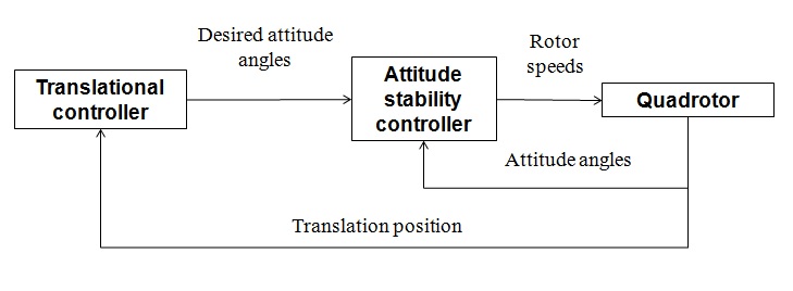
I know how to calculate the attitude stability controller, which relate rotor speed and desired angles. However, I have no clear at all how to implement the translational controller transfer function, whose output is the desired angle that the rotors must achieve considering the position I want to translate.

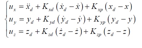
Considering that two controllers are PD, how can you calculate the translational controller transfer function and include it in the system? Time domain equations in the outer loop are next, where U terms relate to the thrust axis components. Thanks
enter image description here

$\endgroup$

2 Answers 2

1
$\begingroup$

You have the equations (although I don't understand your $\ddot x$ term in the position equation). You just need to take it into the frequency domain, where a time derivative is $s$ times the variable, and solve for output over input $\vec x \over \vec u$. If you search for state space transfer functions it should be straightforward.

$\endgroup$
8
  • $\begingroup$ Thx, formula above is taken out from here. Should everything (inner and outer loop) be multiplied for the total transfer function? In the simulations I made with quadrotors I added x acceleration term and work. $\endgroup$
    – galtor
    Commented Apr 5, 2016 at 12:25
  • $\begingroup$ without looking at the paper, I believe the $\ddot x_d$ term is the nominal acceleration at the desired point on the trajectory galtor's quad will be following. $\endgroup$
    – holmeski
    Commented Apr 5, 2016 at 12:45
  • $\begingroup$ Yes, but I don't believe putting an acceleration term in the position equation is correct (compare the equation for $u_x$ to $u_y$ and $u_z$).. $\endgroup$
    – SteveO
    Commented Apr 5, 2016 at 15:41
  • $\begingroup$ i believe that $y_d$ and $z_d$ are typos and should also be nominal acceleration. $\endgroup$
    – holmeski
    Commented Apr 5, 2016 at 17:01
  • $\begingroup$ without the nominal acceleration the system will not be able to track the trajectory even if we assume that the attitude controller can perfectly track the desired attitude (solved for using the relation in my answer) when there is acceleration in the trajectory. $\endgroup$
    – holmeski
    Commented Apr 5, 2016 at 17:05
1
$\begingroup$

If your $u_x$, $u_y$, and $u_z$ terms are desired accelerations, and it looks like they are, then the quad would be commanded to an attitude where those accelerations can be achieved. So

$ \ddot x_{vehicle} = T_{vehicle}^T *F_{throttle} - g$

where $\ddot x_{vehicle}$ is the acceleration of the vehicle in the inertial frame and $T_{vehicle}$ is the transformation from the inertial frame to the vehicle frame. This is the equation relating the output of the position controller to the input of the attitude controller. It allows you to solve for the desired attitude and throttle (which you seem to be missing from your system).

- the real answer to your question is that you will not be able to get a transfer function relating desired position to commanded attitude because the transformation in the equation above is nonlinear.

$\endgroup$
1
  • $\begingroup$ I found this thread. Yes, in my simulation I do use desired accelerations, which for me are the derivate of the desired velocity (numerical integration). Desired velocity is the required velocity to reach to my goal position. I get my quadrotor to stop when achieved the desired position in this way, which was the objective $\endgroup$
    – galtor
    Commented Apr 5, 2016 at 13:30

Your Answer

By clicking “Post Your Answer”, you agree to our terms of service and acknowledge you have read our privacy policy.

Not the answer you're looking for? Browse other questions tagged or ask your own question.