3
$\begingroup$

I'm hoping to move a plate (3MM x 45MM) back and forth using a DC motor. Here's my idea so far:

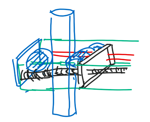
enter image description here

The motor drives a threaded shaft which is attached on one side of the plate. To help alignment, a rod is added to the other side of the plate (red). My guess is that if it's just a rod in a through hole, it could potentially jam.

AFAIK, usually, in bigger setups, a linear bearing would come in handy. However, given that the plate is just 3MM thick, are there better ways to help alignment? Could making the edge around the through hole like the inside of a donut help? Something like

enter image description here

Is it easy to make? In fact, is my concern actually valid?

Thanks

EDIT The centre area of the plate needs to be kept clear. This is intended to be part of a (~10MM thick) pole climber, where several guide rollers are fitted on the left side of the plate and a motor driven roller is on the left of the part (not depicted). So the idea is the press the guide roller against the pole until the two rollers have a good grip on the pole. The whole car is fairly light, so the force expected is around 30N.

Here's a more complete depiction:

enter image description here

The rollers are spring loaded, but they need to be released and retracted - and adjusted for different pole widths.

$\endgroup$
4
  • $\begingroup$ It might be easier to use climbing-U's, like in daijiworld picture from a page re “scale electric poles easily $\endgroup$ Commented Dec 31, 2015 at 19:27
  • $\begingroup$ Side note: have you seen inkscape? You could get much cleaner images with it, and quite quickly too! $\endgroup$
    – Shahbaz
    Commented Jan 5, 2016 at 15:30
  • $\begingroup$ Why do you need to do this with a DC Motor? As far as I can tell from your final image, this is just the pole thickness adjustment. Why not do this manually? $\endgroup$ Commented Jan 7, 2016 at 19:42
  • $\begingroup$ That's because I'm trying to have the process automated. $\endgroup$
    – Kar
    Commented Jan 8, 2016 at 4:00

5 Answers 5

2
$\begingroup$

From the sound of it you require smooth continuous operation in this application. To guarantee this you can use a bearing (cheap $3-5 USD ebay bearings would be fine unless you have non-trivial load needs). In your case the load is radial. Depending which bearing you use, you can get around 20 degrees of misalignment (depending on fit and material) before the interface will jam.

Smoothing the interface between the guide axles and plate would possibly suffice depending on what material the interfacing components are made of, and how much load the interface should carry. The less friction between the interfacing parts, the more smoothly it will slide. A low-friction polymer (e.g. PTFE) would be good for this.

Your suggestion to put a fillet radius on the interface edges would allow a greater misalignment between parts, however may not reduce friction significantly (unless one of the parts is significantly deformable under sliding conditions).

You should aim to reduce friction by picking your materials to have low frictional coefficients, also a small radius to allow slight misalignment, according to your manufacturing techniques and errors.

Edit:

Because your plate is thin and you may have trouble pressing a bearing into it, you should use a flange-mounted bearing like one of these.

$\endgroup$
6
  • $\begingroup$ The black piece is just 3MM thick so I'm not sure if I could fit a bearing on it. Could I make the red a threaded shaft ans gear the two shafts together? Both shafts will then turn at the same rate with no chance of jamming or misalignment - right? $\endgroup$
    – Kar
    Commented Dec 29, 2015 at 11:34
  • $\begingroup$ That sounds like a plausible solution but I think it adds needless complexity and cost. Using a flange-mounted bearing (see edit) should work for your 3mm plate if it is reasonably rigid under load. $\endgroup$
    – Gouda
    Commented Dec 29, 2015 at 11:44
  • $\begingroup$ The load on the bearing is from the weight force of the plate, so it is a radial force. An axial force would mean that there is something pushing on the bearing in the direction of the the guide axle. You may be mistaking the axial movement of the plate for an axial load on the bearing (see the first link in the answer). However, some ball-bearings with axial motion may not be suited to sliding interfaces, so for your low-load application I'd suggest a polymer sliding bearing. $\endgroup$
    – Gouda
    Commented Dec 29, 2015 at 12:41
  • $\begingroup$ I've been staring at the first link for quite some time now, but I can't quite get the diagrams. I looked it up elsewhere and found this. So, with radial bearings, isn't the shaft supposed to rotate about the bearing's axis of rotation? That is, a radial bearing is just a skateboard wheel. In my case, the bearing is supposed to slide along the shaft though, so won't a radial bearing end up gripping on the shaft? Sorry for being so thick! $\endgroup$
    – Kar
    Commented Dec 29, 2015 at 13:02
  • $\begingroup$ No problem, I'm not an expert on this either, I think there may be some bad nomenclature that has stuck. A radial bearing is one that bears a mainly radial load. The bearing may be rolling-element or plain (or other see en.wikipedia.org/wiki/Bearing_(mechanical)#Types ). Ball-bearings are a rolling-element bearing, which may bite into the material, however a plain-type bearing cannot. $\endgroup$
    – Gouda
    Commented Dec 29, 2015 at 13:17
2
$\begingroup$

Your setup is prone to binding because of the physical arrangement. You have the leadscrew on one side and the bearing on the other, so the leadscrew is unevenly supported.

I would put the leadscrew in the middle, with rails on either side. Then, instead of a bearing, I would use bushings, which you could just epoxy in place.

How prone to jamming this is depends on your alignment, tolerances, and the load you place on the plate.

:EDIT:

Now that I see your application, can you not just use a spring? Does it need to grab/release the pole on its own or can you pull a spring-loaded wheel platform back, put it on the pole, then release it?

$\endgroup$
6
  • $\begingroup$ I see what you mean. I need to have clear space between the plates in the middle so I can't fit a lead screw there, unfortunately. How about another lead screw on the other side and the two are geared together? Also, why bushings rather than bearings? $\endgroup$
    – Kar
    Commented Dec 29, 2015 at 14:23
  • $\begingroup$ @Kar - that would work too, but would be more expensive. Bushings are technically still bearings, but the term generally implies lower force, lower cost than a similar bearing, and bushings tend to rub directly with a shaft, where a bearing typically has an inner race that makes fixed contact with the shaft and then inner and outer races rub together. $\endgroup$
    – Chuck
    Commented Dec 29, 2015 at 14:41
  • $\begingroup$ I see. Would you say that one lead screw on each side, geared together, is likely the simplest method if the centre area is to be kept clear? $\endgroup$
    – Kar
    Commented Dec 29, 2015 at 14:44
  • 1
    $\begingroup$ @Kar - Maybe, but you haven't given any other information about what this is used for, how much weight your moving, positioning accuracy, speed, length of stroke - you haven't really given any information that would be required to actually design anything. You've said, "here's some dimensions, is this okay?", and it's not really possible to give a lot of useful advice with that. $\endgroup$
    – Chuck
    Commented Dec 29, 2015 at 15:57
  • $\begingroup$ You could use a carriage system, like a print head, that uses a driven pulley on one side and an idler on the other. That would give you (essentially) infinite stroke, accurate to the resolution on your encoder, but it may not be able to provide the force you need. Ultimately, for better evaluation, you need to provide more information. $\endgroup$
    – Chuck
    Commented Dec 29, 2015 at 15:57
1
$\begingroup$

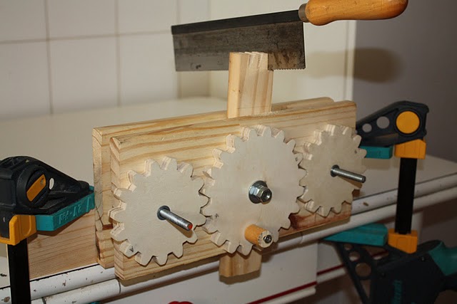
Instead of a threaded rod and a non-threaded rod, use two threaded rods (i.e. replace the red rod in your diagram with a threaded rod) and drive them both from the same motor. You're basically building a twin screw vise.

twin screw vise

You can also do this with gears:

geared twin drive vise

$\endgroup$
1
$\begingroup$

Another, similar, configuration is a linear actuator along the center axis of the plate with two guide rails one on both side of the plate. As said by @Chuck this would help with alignment.

There are many DC actuators, such as Actuonix Motion Devices (formerly Firgelli Technologies) here.

Instead of DC motor, you can use stepper linear actuators such as these from Haydon Kerk, using the captive style. They have a good range of thrust force options among the different motor sizes.

$\endgroup$
0
$\begingroup$

You may be able to find readily-available off the shelf solutions for your implementation. Look at the offerings by companies such as Thompson, Igus and the like.

http://www.thomsonlinear.com/website/com/eng/products/lms.php

http://www.igus.com/Drylin?C=US&L=en

There are integrated assemblies, both belt driven and lead-screw driven, that would eliminate the issue you are having in trying to design a custom solution. There are also links to "dry" linear bearings on the Igus page, which would support the axial motion you are concerned with, in the event you do need to design a custom mechanical subsystem.

$\endgroup$
2
  • $\begingroup$ The existing stuff seem to be fairly expensive; that's why I'm trying to make my own. It won't be as good, but (hopefully) it won't cost me an arm and a leg. $\endgroup$
    – Kar
    Commented Dec 29, 2015 at 19:33
  • $\begingroup$ That is understandable. You may be able to study some of the off the shelf products to come up with solution concepts that address your alignment, spacing, and size concerns. $\endgroup$
    – SteveO
    Commented Dec 29, 2015 at 19:35

Your Answer

By clicking “Post Your Answer”, you agree to our terms of service and acknowledge you have read our privacy policy.

Not the answer you're looking for? Browse other questions tagged or ask your own question.