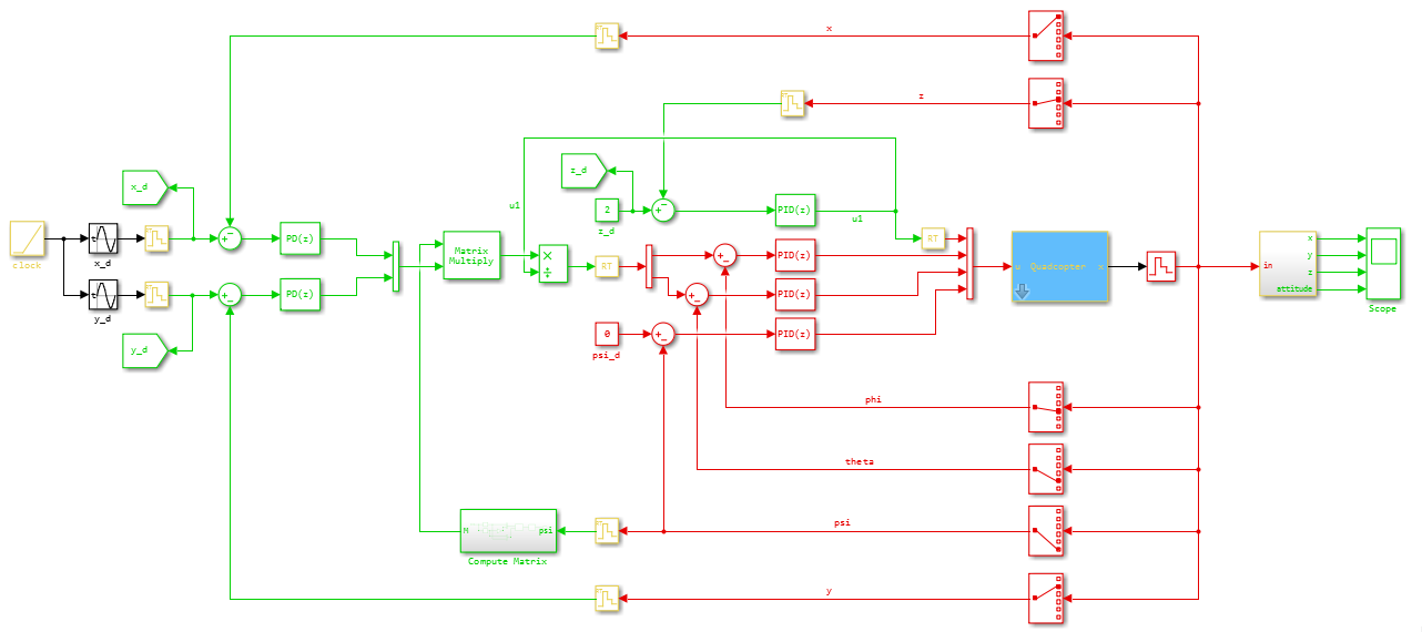
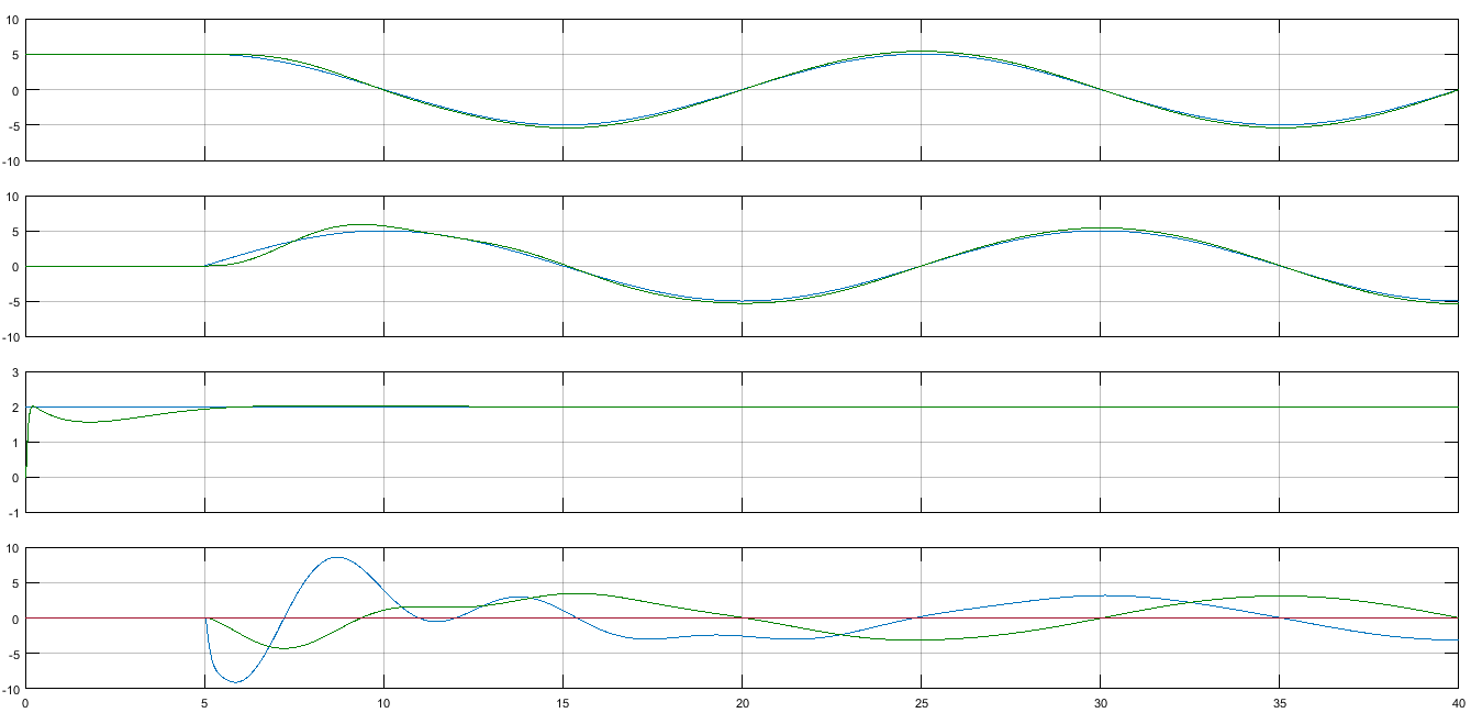
The quadrotor system is multi-ODEs equations. The linearized model is usually used especially for position tracking, therefore one can determine the desired x-y positions based on the roll and pitch angles. As a result, one nested loop which has inner and outer controllers is needed for controlling the quadrotor. For implementation, do I have to put while-loop inside ode45 for the inner attitude controller? I'm asking this because I've read in a paper that the inner attitude controller must run faster (i.e. 1kHz) than the position controller (i.e. 100-200 Hz). In my code, both loops run at 1kHz, therefore inside ode45 there is no while-loop. Is this correct for position tracking? If not, do I have to insert while-loop inside ode45 for running the inner loop? Could you please suggest me a pseudocode for position tracking?
To be more thorough, the dynamics equations of the nonlinear model of the quadrotor is provided here, if we assume the small angles, the model is reduced to the following equations
$$ \begin{align} \ddot{x} &= \frac{U_{1}}{m} ( \theta \cos\psi + \phi \sin\psi) \\ \ddot{y} &= \frac{U_{1}}{m} ( \theta \sin\psi - \phi \cos\psi) \\ \ddot{z} &= \frac{U_{1}}{m} - g \\ \ddot{\phi} &= \frac{l}{I_{x}} U_{2} \\ \ddot{\theta} &= \frac{l}{I_{y}} U_{3} \\ \ddot{\psi} &= \frac{1}{I_{z}} U_{4} \\ \end{align} $$
The aforementioned equations are linear. For position tracking, we need to control $x,y,$ and $z$, therefore we choose the desired roll and pitch (i.e. $\phi^{d} \ \text{and} \ \theta^{d}$)
$$ \begin{align} \ddot{x}^{d} &= \frac{U_{1}}{m} ( \theta^{d} \cos\psi + \phi^{d} \sin\psi) \\ \ddot{y}^{d} &= \frac{U_{1}}{m} ( \theta^{d} \sin\psi - \phi^{d} \cos\psi) \\ \end{align} $$
Therefore, the closed form for the desired angles can be obtained as follows
$$ \begin{bmatrix} \phi_{d} \\ \theta_{d} \end{bmatrix} = \begin{bmatrix} \sin\psi & \cos\psi \\ -\cos\psi & \sin\psi \end{bmatrix}^{-1} \left( \frac{m}{U_{1}}\right) \begin{bmatrix} \ddot{x}^{d} \\ \ddot{y}^{d} \end{bmatrix} $$
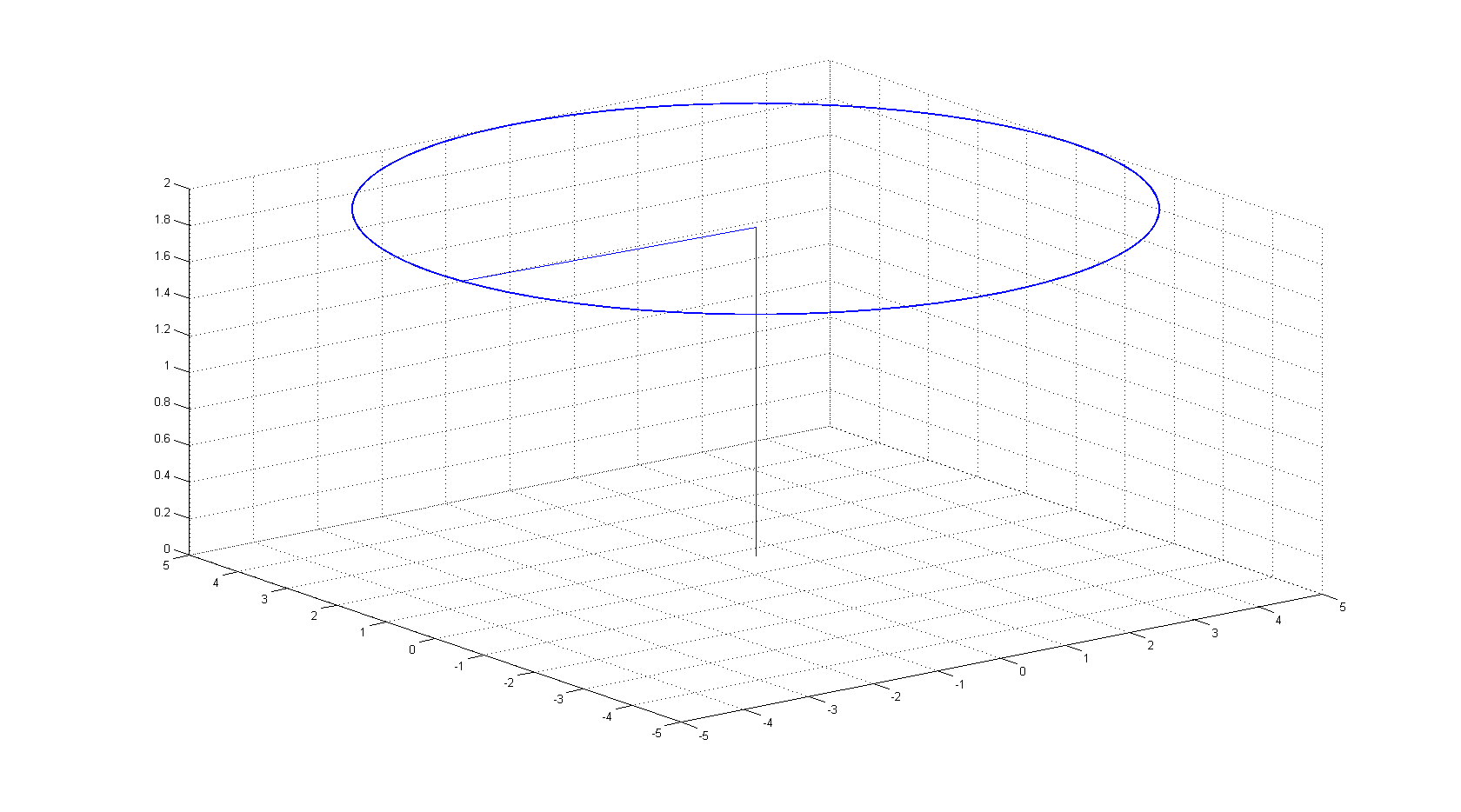
My desired trajectory is shown below
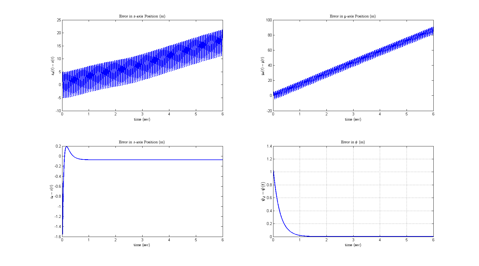
The results are
And the actual trajectory vs the desired one is
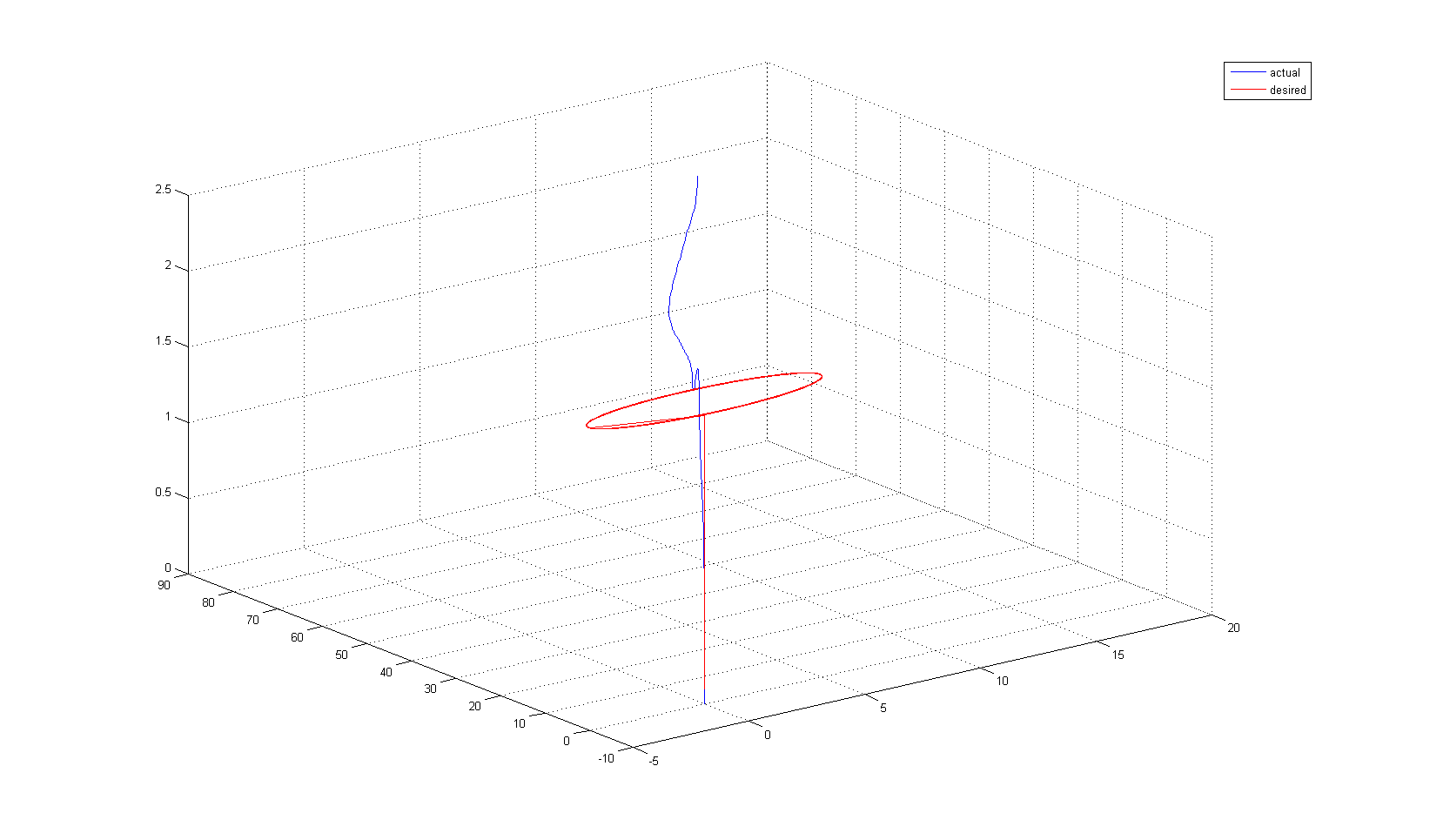
My code for this experiment is
%%
%######################( Position Controller )%%%%%%%%%%%%%%%%%%%%%%%%%%%%%

clear all;
clc;

dt = 0.001;
 t = 0;

% initial values of the system
 x = 0;
dx = 0;
 y = 0;
dy = 0;
 z = 0;
dz = 0;

   Phi = 0;
  dPhi = 0;
 Theta = 0;
dTheta = 0;
   Psi = pi/3;
  dPsi = 0;


%System Parameters:
m  = 0.75;      % mass (Kg)
L  = 0.25;      % arm length (m)
Jx = 0.019688; % inertia seen at the rotation axis. (Kg.m^2)
Jy = 0.019688; % inertia seen at the rotation axis. (Kg.m^2)
Jz = 0.039380; % inertia seen at the rotation axis. (Kg.m^2)
g  = 9.81;      % acceleration due to gravity m/s^2

errorSumX = 0;
errorSumY = 0;
errorSumZ = 0;

errorSumPhi   = 0;
errorSumTheta = 0;

pose = load('xyTrajectory.txt');

DesiredX = pose(:,1);
DesiredY = pose(:,2);
DesiredZ = pose(:,3);

dDesiredX = 0;
dDesiredY = 0;
dDesiredZ = 0;

DesiredXpre = 0;
DesiredYpre = 0;
DesiredZpre = 0;

dDesiredPhi = 0;
dDesiredTheta = 0;
DesiredPhipre = 0;
DesiredThetapre = 0;


for i = 1:6000

   % torque input
   %&&&&&&&&&&&&( Ux )&&&&&&&&&&&&&&&&&&
   Kpx = 50; Kdx = 8; Kix = 0;
   Ux = Kpx*( DesiredX(i) - x  ) + Kdx*( dDesiredX - dx ) + Kix*errorSumX;

   errorSumX = errorSumX + ( DesiredX(i) - x );

     dDesiredX = ( DesiredX(i) - DesiredXpre ) / dt;
   DesiredXpre = DesiredX(i);

   %&&&&&&&&&&&&( Uy )&&&&&&&&&&&&&&&&&&
   Kpy = 100; Kdy = 10; Kiy = 0;
   Uy = Kpy*( DesiredY(i) - y  ) + Kdy*( dDesiredY - dy ) + Kiy*errorSumY;


   errorSumY = errorSumY + ( DesiredY(i) - y );

     dDesiredY = ( DesiredY(i) - DesiredYpre ) / dt;
   DesiredYpre = DesiredY(i);


   %&&&&&&&&&&&&( U1 )&&&&&&&&&&&&&&&&&&
   Kpz = 100; Kdz = 20; Kiz = 0;
   U1 = Kpz*( DesiredZ(i) - z ) + Kdz*( dDesiredZ - dz ) + Kiz*errorSumZ;

   errorSumZ = errorSumZ + ( DesiredZ(i) - z );

      dDesiredZ = ( DesiredZ(i) - DesiredZpre ) / dt;
   DesiredZpre = DesiredZ(i);

   %#######################################################################
   %#######################################################################
   %#######################################################################
   % Desired Phi and Theta
   R = [  sin(Psi),cos(Psi);
         -cos(Psi),sin(Psi)];


   DAngles = R\( (m/U1)*[Ux; Uy]);


   %Wrap angles
   DesiredPhi   = wrapToPi( DAngles(1) ) /2;
   DesiredTheta = wrapToPi( DAngles(2) );


   %&&&&&&&&&&&&( U2 )&&&&&&&&&&&&&&&&&&
   KpP = 100; KdP = 10; KiP = 0;
   U2 = KpP*( DesiredPhi - Phi ) + KdP*( dDesiredPhi - dPhi )  + KiP*errorSumPhi;

   errorSumPhi = errorSumPhi + ( DesiredPhi - Phi );

     dDesiredPhi = ( DesiredPhi - DesiredPhipre ) / dt;
   DesiredPhipre = DesiredPhi;


   %--------------------------------------
   %&&&&&&&&&&&&( U3 )&&&&&&&&&&&&&&&&&&

   KpT = 100; KdT = 10; KiT = 0;
   U3 = KpT*( DesiredTheta - Theta ) + KdP*( dDesiredTheta - dTheta ) + KiT*errorSumTheta;

    errorSumTheta = errorSumTheta + ( DesiredTheta - Theta );

     dDesiredTheta = ( DesiredTheta - DesiredThetapre ) / dt;
   DesiredThetapre = DesiredTheta;


   %--------------------------------------
   %&&&&&&&&&&&&( U4 )&&&&&&&&&&&&&&&&&&
   KpS = 80; KdS = 20.0; KiS = 0.08;
   U4 = KpS*( 0 - Psi ) + KdS*( 0 - dPsi );


   %###################( ODE Equations of Quadrotor )###################
   %===================( X )=====================
   ddx = (U1/m)*( Theta*cos(Psi) + Phi*sin(Psi) );

    dx = dx + ddx*dt;
     x =  x +  dx*dt;
   %===================( Y )=====================
   ddy = (U1/m)*( Theta*sin(Psi) - Phi*cos(Psi) );

    dy = dy + ddy*dt;
     y =  y +  dy*dt;

   %===================( Z )=====================
   ddz = (U1/m) - g;

    dz = dz + ddz*dt;
     z =  z +  dz*dt;

   %===================( Phi )=====================
   ddPhi = ( L/Jx )*U2;

    dPhi = dPhi + ddPhi*dt;
     Phi =  Phi +  dPhi*dt;

   %===================( Theta )=====================
   ddTheta =  ( L/Jy )*U3;

    dTheta =  dTheta + ddTheta*dt;
     Theta =   Theta +  dTheta*dt;

   %===================( Psi )=====================
   ddPsi =  (1/Jz)*U4;

    dPsi = dPsi + ddPsi*dt;
     Psi =  Psi +  dPsi*dt;

   %store the erro
     ErrorX(i)   = ( x - DesiredX(i) );
     ErrorY(i)   = ( y - DesiredY(i) );
     ErrorZ(i)   = ( z - DesiredZ(i) );
%    ErrorPhi(i)   = ( Phi - pi/4 );
%    ErrorTheta(i) = ( Theta - pi/4 );
     ErrorPsi(i)   = ( Psi - 0 );


   X(i) = x;
   Y(i) = y;
   Z(i) = z;

   T(i) = t;

%    drawnow
%    plot3(DesiredX, DesiredY, DesiredZ, 'r')
%    hold on
%    plot3(X, Y, Z, 'b')
   t = t + dt;


end


Figure1 = figure(1);
set(Figure1,'defaulttextinterpreter','latex');
%set(Figure1,'units','normalized','outerposition',[0 0 1 1]);

subplot(2,2,1)
plot(T, ErrorX, 'LineWidth', 2)
title('Error in $x$-axis Position (m)')
xlabel('time (sec)')
ylabel('$x_{d}(t) - x(t)$', 'LineWidth', 2)

subplot(2,2,2)
plot(T, ErrorY, 'LineWidth', 2)
title('Error in $y$-axis Position (m)')
xlabel('time (sec)')
ylabel('$y_{d}(t) - y(t)$', 'LineWidth', 2)

subplot(2,2,3)
plot(T, ErrorZ, 'LineWidth', 2)
title('Error in $z$-axis Position (m)')
xlabel('time (sec)')
ylabel('$z_{d} - z(t)$', 'LineWidth', 2)


subplot(2,2,4)
plot(T, ErrorPsi, 'LineWidth', 2)
title('Error in $\psi$ (m)')
xlabel('time (sec)')
ylabel('$\psi_{d} - \psi(t)$','FontSize',12);
grid on


Figure2 = figure(2);
set(Figure2,'units','normalized','outerposition',[0 0 1 1]);

figure(2)
plot3(X,Y,Z, 'b')
grid on

hold on
plot3(DesiredX, DesiredY, DesiredZ, 'r')

pos = get(Figure2,'Position');
set(Figure2,'PaperPositionMode','Auto','PaperUnits','Inches','PaperSize',[pos(3),pos(4)]);
print(Figure2,'output2','-dpdf','-r0');

legend('actual', 'desired')
The code of the desired trajectory is
clear all; clc;

fileID = fopen('xyTrajectory.txt','w');

 angle = -pi; radius = 5; z = 0; t = 0;

for i = 1:6000
    if ( z < 2 )
        z = z + 0.1;
        x = 0;
        y = 0;
    end
    if  ( z >= 2 )
        angle = angle + 0.1;
        angle = wrapToPi(angle);
        x = radius * cos(angle);
        y = radius * sin(angle);
        z = 2;
    end

    X(i) = x;
    Y(i) = y;
    Z(i) = z;

    fprintf(fileID,'%f \t %f \t %f\n',x, y, z); end

fclose(fileID); plot3(X,Y,Z) grid on
