2
$\begingroup$

I want programme my very own G-code generator for my final year electrical engineering project. I know that there are many open source G-code generators out there, but I need a G-code generator which generates a G-codes for custom circuit designs drawn by the user and pass the G-code serially to my 2 axis CNC machine. So currently I'm working on a Qt based GUI where I draw .dxf format circuit diagrams and electrical components (like resistors, capacitors) and when I press a "Generate G-code" push button I should generate a text file with nice set of G-codes for my designed diagram.

So the problem here is, how do I generate the G-code? Is there any specific algorithm to follow or adapt? I tried googling for G-code generator algorithm but I couldn't find any helpful stuff.

$\endgroup$
4
  • $\begingroup$ Is this for a pick-and-place machine for electrical components, or to mill the traces of a PCB? $\endgroup$
    – Ben
    Commented Oct 30, 2014 at 23:28
  • $\begingroup$ There's a few algorithms and other ideas related to generating G-code for electronic circuits in the PCB milling and Automated Circuitry Making pages on the RepRap wiki. $\endgroup$
    – David Cary
    Commented Oct 31, 2014 at 1:52
  • $\begingroup$ @Ben Basically a xy-plotter machine which sketches the circuits $\endgroup$
    – Vino
    Commented Oct 31, 2014 at 16:46
  • $\begingroup$ @David Cary Thank you bro, ill have a look at it. $\endgroup$
    – Vino
    Commented Oct 31, 2014 at 16:47

2 Answers 2

2
$\begingroup$

I assume you know (or can figure out) how to parse the line objects in the dxf file, and can convert them to straight line operations in g-code. So the basic problem is how to order the operations to minimize time (which is the same as unnecessary travel).

This sounds like a variant of the Travelling Salesman Problem. Except instead of visiting nodes, you traverse edges (the lines in your circuit). So there is probably no efficient solution to the problem.

I assume that once you are tracing a line, you don't want to stop until the line ends. This is to avoid unnecessary pen-up, pen-down operations. I guess a greedy solution would probably be fine. I envision the algorithm to be something like this:

given a list of lines with endpoints:

0. if list is empty: end
1. Pick a line and endpoint, go there, pen down.  
   (you might want to use a heuristic here such as pick the closest point to where you are).
2. go to other endpoint, delete line from list
3. search through list of lines and find a new line with same endpoint.  
   (you might want to use a heuristic here to continue going straight if you can).
  if you found one: goto 2
  else: pen up, goto 0
$\endgroup$
2
  • $\begingroup$ I think the problem is considerably harder than that. Remember, we're not drawing out the tracks that are defined in the DXF file, we're cutting away the space in-between the tracks. $\endgroup$ Commented Oct 31, 2014 at 22:35
  • $\begingroup$ No, for my case I'm actually drawing out the tracks. Thank you so much for answering my query. Much appreciate! $\endgroup$
    – Vino
    Commented Nov 1, 2014 at 22:04
2
$\begingroup$

This is not a trivial problem to solve. Assuming your DXF file contains various primitives like tracks and pads drawn out, you need to create an algorithm which draws cuts around them, to end up with a PCB something like this:
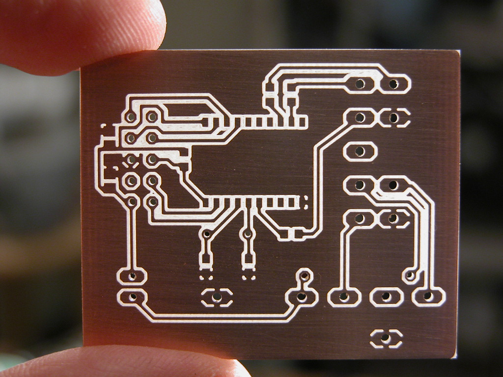
CNC cut PCB

This is known as PCB isolation routing, and is in itself is non-trivial because (I assume) the tracks and pads will overlap in places, and so the algorithm has to be sure not to cut all the way around every primitive, but to cut around them in so far as to avoid cutting through any of them.
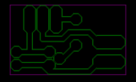
CNC cut PCB toolpaths

There are two ways you can approach this problem:

Vector: The 'best' way is to solve it using vectors. Calculate the set of lines and arc segments around each primitive, calculate where they intersect neighboring lines or arcs, and trim them to length so that they form a continuous loop around the copper net. This is the 'best' because the lines and arcs naturally translate into a simple set of G-Codes. However, it can be a pain to program, and you'll be working out lots of linear algebra, and dealing with a ton of tricky edge cases.

Bitmap: This way produces more bloated G-Code, but is easier to program. Simply render the image of your PCB at high resolution. But for each primitive, draw it wider by the width of the cutting tool, Then write an algorithm which follows the edges around the copper nets, generating G-Code commands as it goes. If you're smart, you can reduce the number of G-Code lines produced by detecting movement in straight lines, and only generating a G-Code command when you turn a corner. If you're really smart, you might even be able to detect arcs too:
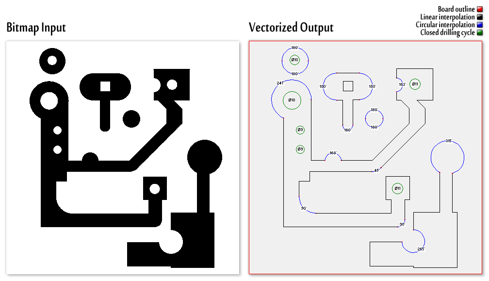
Bitmap to vector conversion

You might want to go the next step and cut out the dead copper to have a PCB like this:
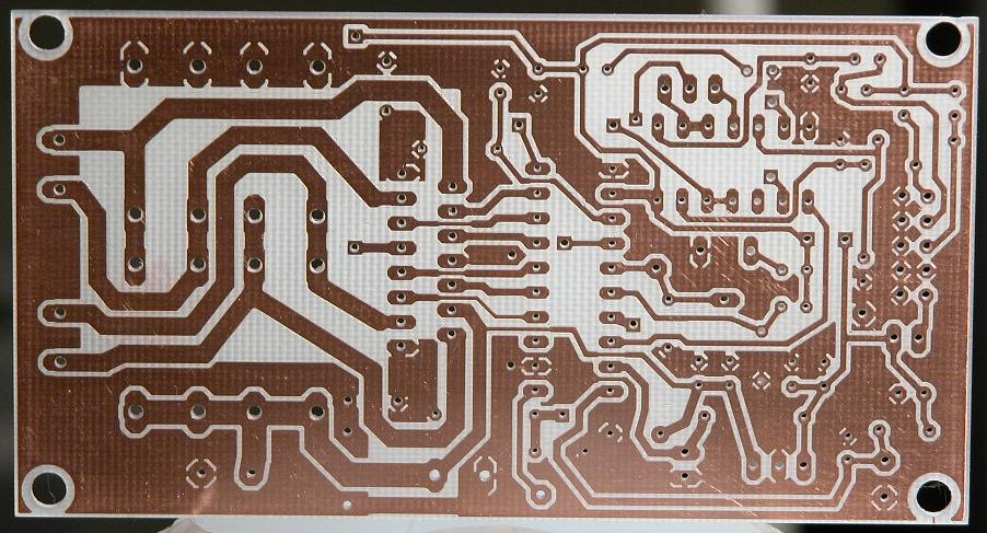
CNC cut PCB

This is only a little harder, and involves offsetting your cutting paths, trimming them against each other, offsetting again, etc. Then finally joining up all of the concentric loops into one continuous path. This example image is not from a PCB, but it's the same principle:
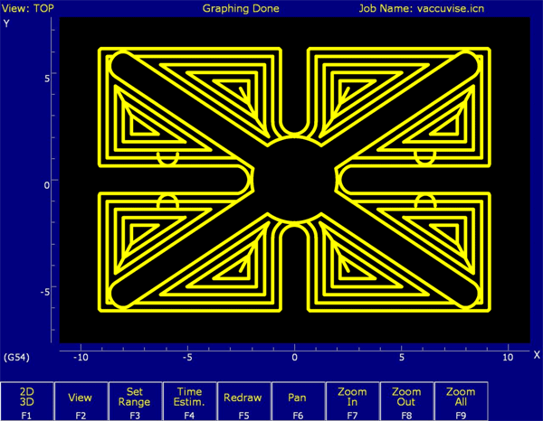
CNC pocketing toolpath

Having written several similar programs, I can tell you from experience that it's not trivial. But it's also not impossibly hard. You'll have to decide how much time you have to spare on this problem. If you have less than a week (though I suggest at least two weeks), then I suggest you try out one of the many source code repositories out there which do this.

$\endgroup$
2
  • $\begingroup$ Thank you so much for answering my query. Much appreciate! $\endgroup$
    – Vino
    Commented Nov 1, 2014 at 22:05
  • $\begingroup$ @VinokanthVelu - You're welcome. Good luck with your project. $\endgroup$ Commented Nov 1, 2014 at 23:00

Your Answer

By clicking “Post Your Answer”, you agree to our terms of service and acknowledge you have read our privacy policy.

Not the answer you're looking for? Browse other questions tagged or ask your own question.