7
$\begingroup$

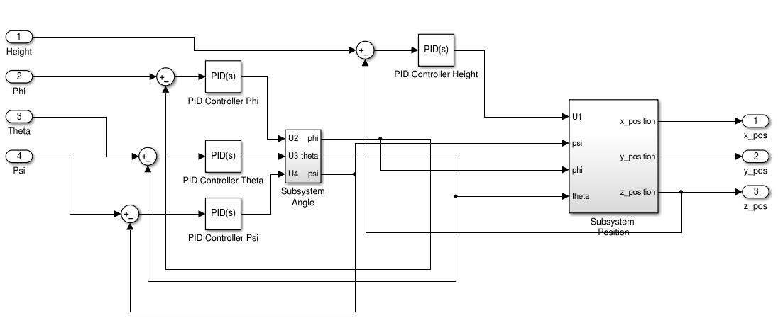
I have a question regarding the implementation of a quadrotor's position controller. In my Matlab model the quadrotor takes 4 inputs: a desired altitude ($Z_{des}$) and desired attitude angles($\Phi_{des}$, $\Theta_{des}$, $\Psi_{des}$) which reflects the motion described by the differential equations of the model (see last picture).

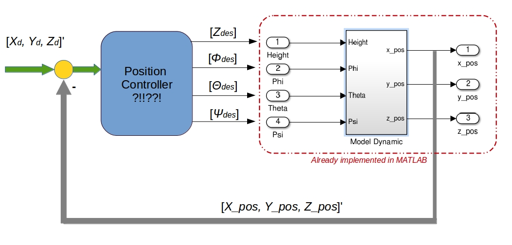
theoretical loop controller for a quadrotor

Here an insight into the implemented Matlab dynamic model. As you can see it has a structure like an inner loop controler:

enter image description here

Anyway...it "hovers" perfectly on the starting point. (perfect graphs :) ) Now I just need to go over and implement a sort of position controller to let the quadrotor to get from a start to a goal point, defined as usual through 3 coordinates $[X_d, Y_d, Z_d]$.

That's tricky because I don't have the same space state variables as input and output of the system. So the controller must take a vector of three coordinates and be able to output 3 different angles to get there. The only exception is the height because it will be simply bypassed by the controller and doesn't need another calculation loop. A different story is for the three angles...

My first idea was to simply create a feedback between the position given at the output of the simulated system and the desired position as in the figure above. But that rises another question: my quadrotor model solves the following equation system:

$$ \large \cases{ \ddot X = ( \sin{\psi} \sin{\phi} + \cos{\psi} \sin{\theta} \cos{\phi}) \frac{U_1}{m} \cr \ddot Y = (-\cos{\psi} \sin{\phi} + \sin{\psi} \sin{\theta} \cos{\phi}) \frac{U_1}{m} \cr \ddot Z = (-g + (\cos{\theta} \cos{\phi}) \frac{U_1}{m} \cr \dot p = \frac{I_{YY} - I_{ZZ}}{I_{XX}}qr - \frac{J_{TP}}{I_{XX}} q \Omega + \frac{U_2}{I_{XX}} \cr \dot q = \frac{I_{ZZ} - I_{XX}}{I_{YY}}pr - \frac{J_{TP}}{I_{YY}} p \Omega + \frac{U_3}{I_{YY}} \cr \dot r = \frac{I_{XX} - I_{YY}}{I_{ZZ}}pq - \frac{U_4}{I_{ZZ}} } $$

that means that they expect (as in the matlab model above) the desired angles and height. But now I need right the inverse: given a desired position calculate the right angles!!! For the direction is the solution really simple, since I can write something like:

Psi = atan2( (yd - yactual), (xd - xactual) );

where y and x lies on the horizontal plane. This is not so simple for the other two angles. So what can I do at this point? Just "invert" the given equations to get the desired angles?

Another idea could be to implement a simple PD or PID controller. This is much more easier given the fact that I can experiment very quickly using Simulink and get very good results. But the problem is here again: how get I the desired angles from a desired position?
$\endgroup$
7
  • $\begingroup$ Related to this question, which is currently unanswered. $\endgroup$
    – Ian
    Commented Oct 7, 2014 at 17:49
  • $\begingroup$ And how do you calculate Vy and/or Vx... And by any chance do you have the source or the paper of this idea?? thanks! $\endgroup$
    – user9337
    Commented Mar 22, 2015 at 20:17
  • $\begingroup$ Look at this paper: link $\endgroup$
    – Wilhelm
    Commented Mar 23, 2015 at 7:49
  • $\begingroup$ I am implementing something similar. I have already implemented my attitude controller but I don't know how to do the position controller. How did you finally implemented it? $\endgroup$
    – user9728
    Commented May 18, 2015 at 9:58
  • $\begingroup$ Any figures or any more information regarding this topic? $\endgroup$
    – ajay
    Commented Jun 14, 2017 at 13:20

2 Answers 2

6
$\begingroup$

By far, the most common solution to this problem is to use 2 separate controllers. The inner loop controller is what you already have: it tracks angle and height commands.

The outer loop controller assumes that the angles are tracked perfectly and treats angles as inputs, rather than separate states. So it takes the position error and converts it to a desired roll/pitch (via PID, just like any other system where you use a controller to calculate desired system inputs), and those desired angles are passed into the inner loop controller.

Make sense?

If you want to get more complicated, your outer loop controller can define a desired acceleration. Using a bit more complicated math you can turn that into desired angles. This is theoretically cleaner but in practice you're still just tuning PID loops so the actual benefit may not justify the time and effort.

------------ EDIT -----------

To elaborate. The outer loop looks something like this. (for simplicity assume yaw=0)

$$ \begin{align} \hat{\phi}^d &= k_{p,y} (y-y^d) + k_{d,y} (v_y - v_y^d) + k_{i,y} \int_0^t (y-y^d) dt \\ \hat{\theta}^d &= -k_{p,x} (x-x^d) = k_{d,x} (v_x - v_x^d) - k_{i,x} \int_0^t (x-x^d) dt \end{align} $$ where $\hat{\phi}^d$ is the desired roll angle and $\hat{\theta}^d$ is the desired pitch angle. When yaw $\ne$ 0 you combine the two. Something like $$ \begin{align} \phi^d &= \cos(\psi) \hat{\phi}^d - sin(\psi) \hat{\theta}^d \\ \theta^d &= \sin(\psi) \hat{\phi}^d + cos(\psi) \hat{\theta}^d \end{align} $$ where $\psi$ is the yaw angle (FYI, I might have the signs wrong there)

Then, in the inner loop you have your existing controller.

$\endgroup$
7
  • $\begingroup$ Yes, it makes sense. The only thing that is not clear to me is: given an outer loop controller which converts position in desired angles, where should I place my PID controller? Your explanation was really clear but it would help if you can put a simple figure to better understand. Thanks! $\endgroup$
    – Wilhelm
    Commented Oct 6, 2014 at 7:06
  • $\begingroup$ The inner/outer loop you meant is something like: Schema Or I am wrong? $\endgroup$
    – Wilhelm
    Commented Oct 6, 2014 at 7:13
  • $\begingroup$ Yes, the diagram you linked to is a similar example of inner/outer loop controllers $\endgroup$
    – ryan0270
    Commented Oct 6, 2014 at 12:13
  • $\begingroup$ ryan. Thanks but it doesn't help me a lot. I should know where to put some PID controllers IN the outer controller. Reagrds $\endgroup$
    – Wilhelm
    Commented Oct 8, 2014 at 12:33
  • $\begingroup$ I edited my answer to show the outer loop equations $\endgroup$
    – ryan0270
    Commented Oct 8, 2014 at 12:47
0
$\begingroup$

I have a suggestion. I have worked some time on px4 controller. For position control, it takes position as input and by feedback (PID) generates desired acceleration. Since quadcopter can generate acce. in Body Z axis , from this preliminary idea u can convert the desired thrust (vector) to attitude command and use the inner loop for attitude controller.

$\endgroup$

Your Answer

By clicking “Post Your Answer”, you agree to our terms of service and acknowledge you have read our privacy policy.

Not the answer you're looking for? Browse other questions tagged or ask your own question.