22
$\begingroup$

The forward kinematics of a robot arm can be solved easily. We can represent each joint using Denavit–Hartenberg transformation matrices.

For example, if the $i^{th}$ joint is a linear actuator, it may have the transformation matrix:

$T_i = \left[\begin{matrix} 1&0&0&0\\ 0&1&0&0\\ 0&0&1&d_i\\ 0&0&0&1 \end{matrix} \right]$ where the extension length is defined by $d_i$

whereas, a rotating link may be:

$T_i = \left[\begin{matrix} 1&0&0&L\\ 0&\cos\alpha_i&-\sin\alpha_i&0\\ 0&\sin\alpha_i&\cos\alpha_i&0\\ 0&0&0&1 \end{matrix} \right]$ where $\alpha$ is the angle, and $L$ is the length of the link.

We can then find the position and orientation of the end effector by multiplying all the transformation matrices: $\prod{T_i}$.

The question is, how do we solve the inverse problem?

Mathematically, for a desired end effector position $M$, find the parameters $d_i$, $\alpha_i$ such that $\prod{T_i} = M$. What methods exist to solve this equation?

$\endgroup$
0

3 Answers 3

13
$\begingroup$

Back in the day, when I was learning, making this up as I went along, I used simple gradient following to solve the IK problem.

In your model, you try rotating each joint each joint a tiny amount, see how much difference that makes to the end point position error. Having done that, you then rotate each joint by an amount proportional to the benefit it gives. Then you do that over and over again until you're close enough.

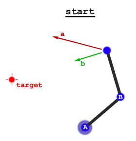
Generally, this is known as gradient following, or hill following. Imagine a robot arm with two degrees of freedom:

IK

Rotating joint A a tiny bit moves the end point in direction a. Rotating joint B a tiny bit moves the end point in direction b. Both of these move us closer to the target by about the same amount, so we should rotate both joints at about the same speed.

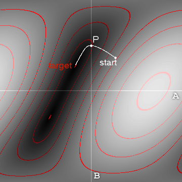
If we were to plot a graph of the distance to the target versus joint angles, it would look like this:

IK

I have coloured in some contours just to help. We can see the path this algorithm takes. What you'll notice is that in joint space, the path taken does not look optimal. It takes a curve. However, in real space, you would see the end point taking a fairly straight line to the target. You can also see that there are actually two solutions to the problem, and the algorithm has just found the closest one.

This is not the only way to solve the inverse kinematics problem. It's certainly not the best way either.

Pros:

  • It's conceptually simple, so great if you're just learnig this.
  • It's easy to implement, even if the sight of Denavit–Hartenberg transformation matrices gives you the frights.
  • It's very general, allowing you to use all kinds of joints: rotary, linear, something else, as long as you can estimate how they cause the end point to move.
  • It copes well, even when there are zero or an infinite number of solutions.

Cons:

  • It's slow, taking many iterations to find the solution. However, it's fine if you can just have the real arm follow the progress of the algorithm as it's calculated.
  • It can get stuck in local minima. I.E. It might not find the best possible solution, if it finds a good enough one.

There are more details about it on my very old web site: The good-looking textured light-sourced bouncy fun smart and stretchy page.

$\endgroup$
2
  • 1
    $\begingroup$ I'm not sure your gradient search will work for more than 2 links. There should be lots of local minima to get stuck in and/or non-unique solutions. $\endgroup$
    – guero64
    Commented Mar 31, 2022 at 13:24
  • $\begingroup$ @guero64 - It works well with more than 2 links. I've had it working perfectly with a 6-DOF robot arm model, and with a model of a tail with about 20 links. $\endgroup$ Commented Mar 31, 2022 at 15:19
5
$\begingroup$

There a number of solutions to this problem that center around the Jacobian Matrix. This slideshow covers the Jacobian methods and also mentions a Cyclic Coordinate Descent method, which I am unfamiliar with.

There are a plethora of resources on the subject - if you ask google for "inverse kinematics Jacobian".

Also, check out Chapter 5.3 of the lecture notes from MIT's Open Course on Introductory Robotics.

$\endgroup$
2
$\begingroup$

There are two broad approaches:

  • analytic solutions, given an end-effector pose, directly compute the joint coordinates. In general the solution is not unique, so you can compute a set of possible joint coordinates. Some may cause the robot to hit things in its environment (or itself), or your task might help you choose a particular solution, ie. you might prefer the elbow to up (or down), or the robot to have its arm to the left (or right) of its trunk. In general there are constraints on obtaining an analytic solution, for 6-axis robots, a spherical wrist (all axes intersect)is assumed. The analytic solutions for many different types of robots have been computed over the decades and you can probably find a paper that gives a solution for your robot.
  • numeric solutions, as described in the other answers, uses an optimisation approach to adjust the joint coordinates until the forward kinematics gives the right solution. Again, there's a huge literature on this, and lots of software.

Using my Robotics Toolbox for MATLAB, I create a model of a well known 6-axis robot using Denavit-Hartenberg parameters

>> mdl_puma560
>> p560

p560 = 

Puma 560 [Unimation]:: 6 axis, RRRRRR, stdDH, fastRNE            
 - viscous friction; params of 8/95;                             
+---+-----------+-----------+-----------+-----------+-----------+
| j |     theta |         d |         a |     alpha |    offset |
+---+-----------+-----------+-----------+-----------+-----------+
|  1|         q1|          0|          0|     1.5708|          0|
|  2|         q2|          0|     0.4318|          0|          0|
|  3|         q3|    0.15005|     0.0203|    -1.5708|          0|
|  4|         q4|     0.4318|          0|     1.5708|          0|
|  5|         q5|          0|          0|    -1.5708|          0|
|  6|         q6|          0|          0|          0|          0|
+---+-----------+-----------+-----------+-----------+-----------+

then choose a random joint coordinate

>> q = rand(1,6)
q =
    0.7922    0.9595    0.6557    0.0357    0.8491    0.9340

then compute the forward kinematics

>> T = p560.fkine(q)
T = 
   -0.9065    0.0311   -0.4210  -0.02271
    0.2451    0.8507   -0.4649   -0.2367
    0.3437   -0.5247   -0.7788    0.3547
         0         0         0         1

Now we can compute the inverse kinematics using a published analytic solution for a robot with 6 joints and a spherical wrist

>> p560.ikine6s(T)
ans =
    0.7922    0.9595    0.6557    0.0357    0.8491    0.9340

and voila, we have the original joint coordinates.

The numerical solution

>> p560.ikine(T)
Warning: ikine: rejected-step limit 100 exceeded (pose 1), final err 0.63042 
> In SerialLink/ikine (line 244) 
Warning: failed to converge: try a different initial value of joint coordinates 
> In SerialLink/ikine (line 273) 

ans =

     []

has failed, and this is a common problem since they typically need a good initial solution. Let's try

>> p560.ikine(T, 'q0', [1 1 0 0 0 0])
ans =
    0.7922    0.9595    0.6557    0.0357    0.8491    0.9340

which now gives an answer but it is different to the analytic solution. That's ok though, since there are multiple solutions to the IK problem. We can verify that our solution is correct by computing the forward kinematics

>> p560.fkine(ans)
ans = 
   -0.9065    0.0311   -0.4210  -0.02271
    0.2451    0.8507   -0.4649   -0.2367
    0.3437   -0.5247   -0.7788    0.3547
         0         0         0         1

and checking that it is the same as the transform we started with (which it is).

Other resources:
$\endgroup$

Your Answer

By clicking “Post Your Answer”, you agree to our terms of service and acknowledge you have read our privacy policy.

Not the answer you're looking for? Browse other questions tagged or ask your own question.