I have upgraded the motors in my robotic arm to sensored, brushless RC car motors. The hope was to reuse the Hall sensors to double as a rotary encoder, by tapping 2 Hall sensors and treating the 2 bits as a quadrature signal (a crude quadrature since 2 of the 4 states will be longer than the other 2).
This works when none of the motor phases are powered and I just rotate the motor manually. But once the stator coils are energized, the encoder no longer counts correctly: When running at low power, the counting is correct, but when running under high power, the count is monotonic (only increases or decreases) no matter if I run in reverse or forward.
I'm almost certain this is because of the stator coils overpowering the permanent magnets on the rotors. So is there still a way to use the Hall sensors as an encoder?
Sorry if this is an obvious question. I'd love to research this problem more if I had more time.
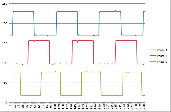
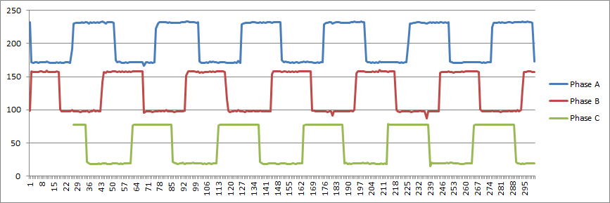
Update: I've measured the wave forms with my DSO quad and see the expected 120 degree separated signals (the measurement for phase C gets more inaccurate over time because I only had 2 probes, so I measured phases A & B first, then A & C, and then merged them.
When ESC speed is 0.1:

When ESC speed is 0.3:

Previously, I was using a hardware quadrature counter (EQEP module on a BeagleBone). At speed=0.3, this was counting backwards no matter if I do forward or reverse!
I then implemented quadrature counting on an LPC1114FN28 uController. The result was still bad at high speeds (count didn't change at all). The logic was:
void HandleGPIOInterrupt()
{
  const uint8_t allowableTransitions[4][2] = {1, 2, 3, 0, 0, 3, 2, 1};
  static int prevState = -1;
  int state = phaseA | (phaseB * 2)
  if (prevState != -1)
  {
    if (allowableTransitions[prevState][0] == state)
    {
       ++rotations;
    }
    else if (allowableTransitions[prevState][1] == state)
    {
      --rotations;
    }
  }
  prevState = state;
}
Then I got the idea to change the code to not update prevState until an expected state happens (to deal with glitches):
  int state = phaseA | (phaseB * 2)
  if (prevState != -1)
  {
    if (allowableTransitions[prevState][0] == state)
    {
       ++rotations;
       prevState = state;
    }
    else if (allowableTransitions[prevState][1] == state)
    {
      --rotations;
      prevState = state;
    }
    else
    {
        // assume transition was a glitch
    }
  }
  else
    prevState = state;
Now the counting finally is correct in both directions, even at speeds higher than 0.3! But are there really glitches causing this? I don't see any in the waveforms?