32
$\begingroup$

I wish to build a robotic arm that can lift a useful amount of weight (such as 3-6 kg on an arm that can extend to approx 1.25 meters). What actuators are available to accomplish this? The main factors and design points are:

  • Not Expensive
  • 5 to 6 DOF
  • to be mounted on a yet to be designed mobile platform
  • battery powered
  • stronger than hobby servos (at least for the 'shoulder' and 'elbow' joints)
  • not slow to actuate
$\endgroup$
1
  • 9
    $\begingroup$ Saw this on SO main in the sidebar, but thought the question was "very strong robot army". Figured I should check in, just in case. $\endgroup$ Commented Nov 7, 2012 at 23:12

6 Answers 6

30
$\begingroup$

Which actuators are suitable for your application depends very much on what kind of robot arm you want to build. Once you have decided on what kind of arm you want you can decide on a suitable actuator for each axis.

The Arm

Assuming from your description that a gantry robot wouldn't be viable, then depending on your specific application, you may want to consider a SCARA arm over an Articulated arm, which is what most people think of when they think Robot arm.

The big advantage of a SCARA arm is that most of it's lifting strength is in it's bearings. The main shoulder, elbow and wrist (yaw) joints are in a flat plane, which means that the motors only need to be strong enough to produce the lateral forces required, they don't need to support the weight of the remaining axes.

The Z axis, pitch and roll (and grip obviously) all have to work against gravity, but the Z axis is easy to gear highly enough to be able to support plenty of weight, and the pitch, roll and grip axes only have to support the payload weight, not the weight of other axes.
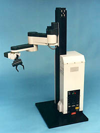
6 UMI RTX robot + gripper

Compare this to an articulated arm, where many of the axes have to support the weight of all axes further down the kinematic chain.
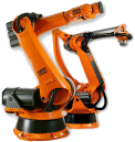
6 Axis Articulated Robots from KUKA

The actuators

Gantry robots

Typically a gantry robot will use linear actuators for the main X, Y & Z axes. These could be low performance, low accuracy, high force actuators such as a lead screw with a servo or stepper drive (force and performance can be traded but accuracy will always be limited by backlash), all the way up to high performance, high accuracy direct drive linear motors with precision encoders.

The remaining 3DOF manipulator will usually require precision rotational motion for pitch, roll and yaw, so usually an electric motor (either stepper or servo), will be most suitable. Even a small motor with a reasonably high gearing can resist gravity against quite high loads.

An aside on servo motors vs. stepper motors

The difference between servo(1) and stepper is a trade-off between complexity and certainty in control.

A servo motor requires an encoder for position feedback, whereas a stepper doesn't. This means that a stepper is electrically much simpler, and from a control point of view simpler if you want low performance.

If you want to get the most out of your motor though (pushing it close to it's limit), then steppers get much more difficult to control predictably. With position feedback on a servo you can tune performance much more aggressively and since you know if it fails to reach it's target position or velocity then your servo loop will get to find out about it and correct it.

With a stepper you have to tune the system so that you can guarantee that it can always make the step, irrespective of the desired speed of move or weight of the payload. Note that some people will suggest adding an encoder to detect missed steps on a stepper motor, but if you are going to do that then you might as well have used a servo motor in the first place!

SCARA arm

With a SCARA arm, the Z axis is probably the only linear axis, while the remaining axes can all be done with rotational motor, so again stepper or servo motor. Sizing these motors is relatively easy because the weight carried is less important to many of them. The motor required to overcome the inertia of a load is rather less than sizing it to overcome gravity.

Articulated arm

With an articulated arm the calculations are more tricky, because most axes will need actuators sized depending on both moving the load and lifting it, but again an electric motor is the easiest to control and use.

The gripper

Finally there is the gripper. This is where I have seen the most variety in actuators. Depending on your applications you could easily use any number of different actuators.

I've used systems with traditional motor driven grippers, linear actuated grippers, piezo flexture grips, pneumatically actuated grippers, vacuum pick-ups and simple slots or hooks amongst others, many of which were specific to the application. What your typical payload is could significantly change the actuator which is best for you. (2)

Doing your calcs

As Rocketmagnet suggests ultimately you are going to have to break out your calculator.

You will need to take into account kinematics of your system, the maximum load on each motor (taking into account the worst case with arm fully extended if you are using an articulate arm design), the speed (a smaller motor with higher gearing might give the force you need without the speed, but a beefier motor might give you a higher torque with lower gearing and a higher speed etc.) and the positional accuracy you need.

In general, the more money you throw at the problem, the better performance (speed, accuracy, power consumption) you will get. But analysing specifications and making smart purchasing decisions can help optimise the price/performance of your robot.

(1) Note that my experience is with industrial servos, typically a brushed or brushless DC motors with a rotary encoder, so this may or may not apply with hobby RC servos.

(2) I would suggest posting another question on this.

$\endgroup$
3
  • $\begingroup$ I'm sorry. my question is mainly about components. Though you made a good point about the design. I hadn't thought about that. Though I still think I wish to use a "standard" arm as in the second picture as I believe it has a better range of motion for being mounted on a mobile platform. $\endgroup$
    – Mark W
    Commented Nov 8, 2012 at 10:19
  • $\begingroup$ but if you are going to do that then you might as well have used a servo motor in the first place! Your post is great but it fails at saying servo or stepper, as a stepper with feedback is a servo!. Also a stepper is a brushless DC motor, and having so much more poles, will produce more torque (with small speed) thus requiring less gear reduction, although less efficient. Also industrial robotic arms tend to have springs to counterbalance or even more force than is needed to counter-balance. $\endgroup$ Commented Jan 8, 2014 at 23:00
  • 1
    $\begingroup$ Whilst you are technically correct @DiegoCNascimento in my experience, in industrial and research settings, stepper motors with encoders are not called servos. Since their performance characteristics, behaviour and control techniques are very different, you don't want someone assuming you mean one when you are talking about the other. This is why here on robotics we try to be explicit about whether we are talking about rcservos, servomotors or stepper-motors. $\endgroup$
    – Mark Booth
    Commented Apr 7, 2014 at 23:42
14
$\begingroup$

When you're choosing actuators, it's instructive to start by calculating how much power you need at the end effector. When you say 'not too slow' you should have some idea what this means, especially under different load conditions.

For example, you might say: 6kg at 0.2m/s and 0kg at 0.5m/s

Now add in the estimated weight of the arm: 10kg at 0.2m/s and 4kg at 0.5m/s

Now calculate the power: 100N * 0.2m/s = 20W and 40N * 0.5m/s = 20W

So the peak power output at the end effector is 20W. You're going to need an actuator which can comfortably produce more than 20W.

I'm going to make assume that you end up deciding to use an electric motor as your actuator. These are still the actuator of choice for powerful electric robots systems. (If you successfully get this robot working with muscle wire without burning down your workshop, I'll eat my mouse).

Since you're using an electric motor, you'll almost certainly be using some kind of gears. Assume the gear train on the motor is about 50% efficient. This means you'll need an electric motor rated for at least 40W. If you want this to be a reliable arm, I'd spec a motor rated for at least 60W.

Next you need to spec the gear train. What's the torque needed? 100N*1.25m = 125Nm. But as usual, you need to spec more torque than this for the gear train, not least because you'll need some spare torque to be able to accelerate the load upwards. Select a gear train which can take more than the rated load.

Lastly, make sure that the motor's torque multiplied by the gear ratio multiplied by the efficiency exceeds your torque requirement, but not the maximum gear load.

$\endgroup$
2
  • 1
    $\begingroup$ What do you mean by but not the maximum gear load? I would interpret that to mean that you shouldn't use a motor which has enough torque to damage your gear train if you accidentally command it to, but it would be better if others didn't have to learn that the hard way. *8') $\endgroup$
    – Mark Booth
    Commented Nov 8, 2012 at 15:46
  • 1
    $\begingroup$ @MarkBooth - That's right. It's quite possible for a motor to break its own gears if the gear ratio is high enough. It's well worth factoring that into the calculation. $\endgroup$ Commented Nov 8, 2012 at 18:07
4
$\begingroup$

Mobile platform: An electro-mechanical linear actuator can be a good choice for light weight actuator which can be mounted on mobile platform.

Battery powered: An electro-mechanical linear actuator is good choice over servo motors, as linear actuators draw power only when it is moving, and it does not need power to hold its position.

5-6 DoF: It might be difficult to achieve this using electro-mechanical linear actuator, as they are mechanical complicated and have limited range of motion

You can try linear actuators from www.firgelli.com. They have miniature linear actuators as well, which are good for small scale application.

Mechanical design concept for arm using linear actuator: Most of earth moving equipment have hydraulic linear actuator. Some of the joints for linear actuator can be implemented in this line.

$\endgroup$
0
3
$\begingroup$

There are two more factors to consider: Complexity and cost.

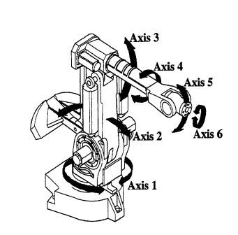
Industrial robotic arm like that

industrial robotic arm http://halcyondrives.com/images/robotic_arm.png
Image from http://halcyondrives.com

normally use torque from the gearbox to direct drive the joint, now think about the torque the gear reduction should support and the size/weight it will be? It simple huge and expensive, their materials need to support a huge torque.

Let's take your example with the arm fully horizontally extended. Lets consider just the load of 6Kg at 1m, you have $ 600Kgf/cm $. This is not including the robot arm own weight (easily more 4Kg), and considering just 1m.

Some solutions industry uses

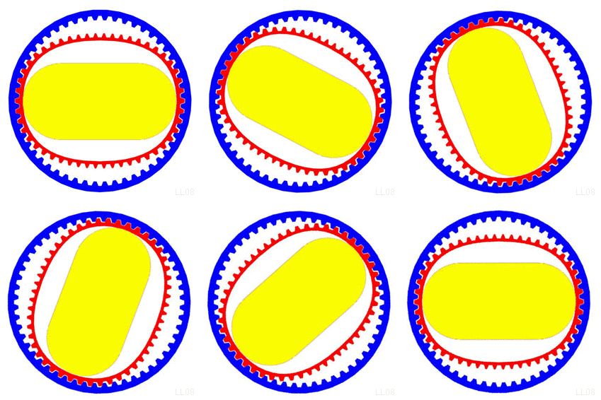
Strain Wave Gearing or Harmonic drive

Strain Wave Gearing or Harmonic drive
Image from http://commons.wikipedia.org

To get lighter gear reduction, with high reduction ratios, most uses Strain Wave Gearing or Harmonic drive. Its low-weight, robust, and according to wikipedia can have a reduction of $ 200:1 $ (wikipedia says more) where a planetary gear can archive $ ~ 10:1 $.

But this type of gearing is very expensive and complex.

Springs and counter-weights

6DOF industrial motor drawing
Image from http://www.globalrobots.ae

Other even simple solution is adding counter-weights like you see in the image. This has a linkage to act both on the forearm (I forget the name) and in the arm. Springs will help too, and if mounted on the same axis of the joint but a bit offset, it will put more force as the arm gets more extended.

Low-cost and less complex solutions for the mechanical drive system

Now for less cost and less complex solutions, what I should think is removing the high torque at the gear drive, so you can use less expensive materials. For a pure electronic drive, this would be a linear actuator.

There is a variety of linear actuators. But the idea is that it will take less force (depending on what points of the arm it is attached).

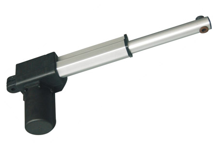
  • "Nut" and leadscrew type

lead screw linear actuator

This type of actuator has many sub-types, and that affects efficiency, wear, force, and much more. But in general, they have a high force and a relative slow-to-medium speed (this will again depend on the type, it can be vary fast, like the ones used on some motion platform simulators).

6 dof motion platform with electric linear actuators http://cfile29.uf.tistory.com/T250x250/195BAD4B4FDB0AF104C30F.

Electric linear actuators are substituting hydraulic linear actuators at this application, and they need to be fast and strong, some simulators easily weight more than 2 tons.

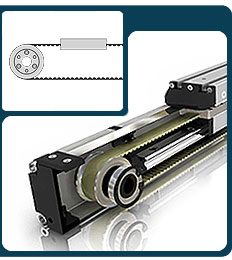
  • Belt or chain drive

For more speed and other simple method are the belt or chain drive like that

belt linear drive actuator
Image from http://images.pacific-bearing.com

This is of course an industrial made one, this is a DIY one, and it has more for the application: (yes it has space for much improvement, but is a good form to show how fast and strong it can be even in this design). http://bffsimulation.com/linear-act.php

This allows you to use less gearing, if a motor could output $ 50Kgf/cm $ and you use a 2 cm diameter pulley, you would get $ 50Kgf $ (not considering losses) on the full stroke.

Also the bearings at this actuator will need to support most radial forces, where in a "leadscrew and nut" the bearing will take most axial force. So depending on the force you need to use a thrust ball bearing.

$\endgroup$
1
$\begingroup$

I think your best bet would be regular hobby servos, if they don't have enough torque, use multiple servos in parallel on the same joint. A good option would be the Dynamixel servos from Robotis but they are more expensive than hobby servos, and you would have to hack the communication protocol as they are controlled by ttl/rs232/rs485, or use a usb2dynamixel(or usb2ax) converter. The advantages are their torque, speed and precision.

$\endgroup$
0
$\begingroup$

You will want to choose low-weight, high torque density actuators for your arms, otherwise the actuators themselves will weigh down your arms and limit performance.

Harmonic drives provide the highest torque per unit weight currently on the market. If you are doing this on a budget, you can probably find some good solutions on eBay. Expect to pay at least $500 or so per joint though. Companies like Harmonic Drive and Leaderdrive manufacture fully integrated actuators, complete with motor, encoder, and gear drive.

$\endgroup$

Your Answer

By clicking “Post Your Answer”, you agree to our terms of service and acknowledge you have read our privacy policy.

Not the answer you're looking for? Browse other questions tagged or ask your own question.