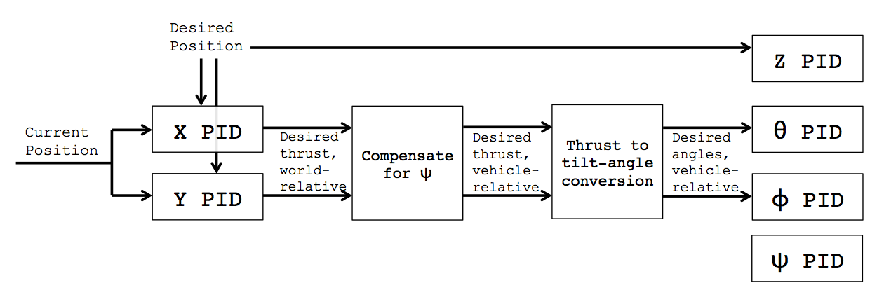
Defining the state of the quadcopter as $\bf{x} = \left[ \begin{matrix} \mathbf{p} & \mathbf{v} & \mathbf{r} & \mathbf{w} \end{matrix} \right]^T$ where $\mathbf{p}$, $\mathbf{v}$, $\mathbf{r}$, and $\mathbf{w}$ are the position, velocity, angular position, and angular velocity of the quadcopter respectively. A simplified transition model for a quadcopter using PD control is:
\begin{align}
\dot{\mathbf{p}} & = \mathbf{v} \\
\dot{\mathbf{v}} & = -g\mathbf{e}_3 + \text{exp}([\mathbf{r}])\mathbf{e}_3u_1/m \\
\dot{\mathbf{r}} & = \mathbf{w} + \frac{1}{2}[\mathbf{r}]\mathbf{w} + (1 - \frac{||\mathbf{r}||}{2\text{tan}(||\mathbf{r}||/2)})\frac{[\mathbf{r}]^2}{||\mathbf{r}||^2}\mathbf{w} \\
\dot{\mathbf{w}} & = \begin{bmatrix} k_1(u_2 - r_x) + k_2w_x \\ k_1(u_3 - r_y) + k_2w_y \\ 0 \end{bmatrix}
\end{align}
where $\mathbf{e}_3 = \left[ \begin{matrix} 0 & 0 & 1 \end{matrix} \right]^T$, $[\mathbf{r}]$ represents the skew-symmetric matrix of $\mathbf{r}$, $||\mathbf{r}||$ represents the magnitude of $\mathbf{r}$, $k_1$ and $k_2$ represent the proportional and derivative gains respectively, and the control $\mathbf{u} = \left[ \begin{matrix} u_1 & u_2 & u_3 \end{matrix} \right]^T$ is comprised of the desired total thrust $u_1$, the desired roll angle $u_2$, the desired pitch angle $u_3$, and assumes yaw remains the same. Note that this uses a PD controller because the integration term I is generally not useful for trajectory following.
Using this model you can, given the current state $\mathbf{x}$, calcualte how the state will change. This of course does not give you the desired angular positions about which you asked. Assuming the user expects the quadcopter to hover once it has reached the specified desired position $\mathbf{p} = [X, Y, Z]^T$ then we need $\mathbf{v} = \mathbf{r} = \mathbf{w} = \left[ \begin{matrix} 0 & 0 & 0 \end{matrix} \right]^T$ for the final state.
However that still does not give you the desired angles to transition between the initial state $\mathbf{x}_i$ and the final state $\mathbf{x}_f = \left[ \begin{matrix} \mathbf{p} & \mathbf{v} & \mathbf{r} & \mathbf{w} \end{matrix} \right]^T$. To get that you need a higher level controller to calculate a trajectory $\pi = (\mathbf{x}[], \mathbf{u}[], \tau)$ with $\mathbf{x} : [0, \tau] \rightarrow \mathcal{X}$, $\mathbf{u} : [0, \tau] \rightarrow \mathcal{U}$ for the state-space $\mathcal{X}$ and control space $\mathcal{U}$ and some travel time $\tau$. This trajectory will give you the desired angles at any given moment.
Unfortunately there are a lot of ways to calculate this trajectory. One possibility is to look at my own work in this area. Specifically my paper titled Kinodynamic RRT*: Asymptotically Optimal Motion Planning for Robots with Linear Dynamics.

