3
$\begingroup$

I have a chip that is labeled L293D with a small 'ST' logo, which does not behave like I believe a L239D should:

I have the chip on a breadboard with pins 4,5,12 and 13 connected to the ground rail. The positive rail gets 6V from a battery pack. A motor is connected to pins 3 and 6. Pin 2 is connected to the positive rail.

Now, when I connect pin 1 (enable 1) to the positive rail, the motor spins, which is expected.

The weird thing is that if I connect pin 16 instead of pin 1 to positive, the motor spins, as well.

Also, with the motor connected to 11 and 14, and 15 connected to positive, the motor spins if I connect pin 1 or pin 16 to positive, but not if I connect pin 9 (which should be the enable pin for that side).

Does any of that make sense? Am I missing something here?

Thanks!
$\endgroup$

2 Answers 2

2
$\begingroup$

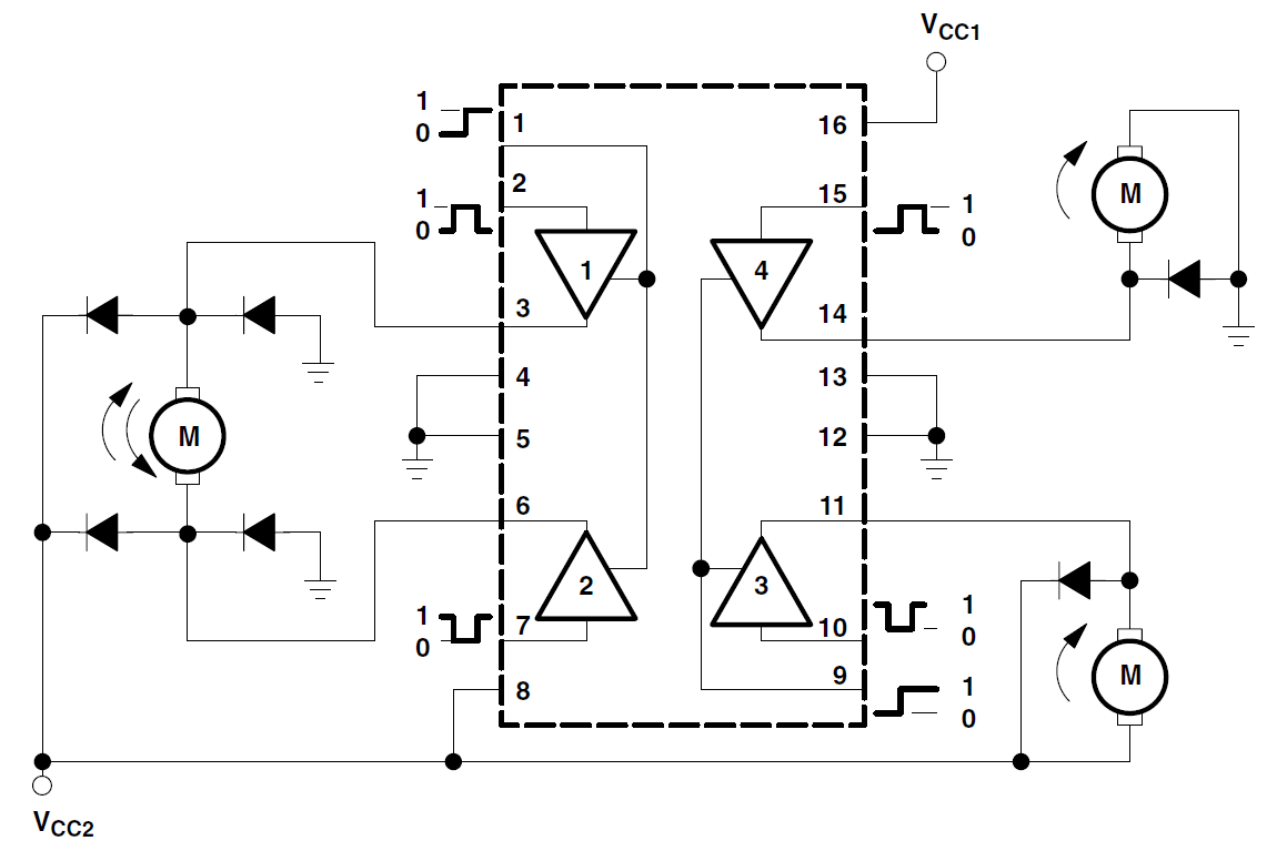
The behaviour you're describing seems to be correct (as described in the Texas Instruments L293 datasheet - which should be the same as ST's variant). Here's an example of how to wire 3 different motors (please note the indicated diodes are internal to the L293).

Copied from TI L293 Datasheet

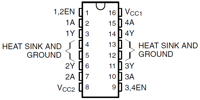
The idea is that Vcc1 (pin 16) should be associated with your logic inputs: pins 1, 2, 7, 9, 10 and 15 (in other words, if your micro is powered from 3V3, Vcc1 should be 3V3). On the other hand, if you run your motors from 6V, Vcc2 (pin 8) should be 6V (or whichever voltage you use to drive the motors).

For reference, here's the pinout of the TI L293.

enter image description here

Update:

The TI variant does indeed seem to be the same as ST's L293D (see powerdip package).

$\endgroup$
0
0
$\begingroup$

The correct way to wire the pins out on a L293D is as follows:
Pin 1 & 9 are enable pins should be tied to +5 if pulled low the outputs will be turned off regardless of the input states.
Pins 4,5, 13, 12 are ground pins and ideally connected to the micro-controller ground connection.
Pin2, Pin7, Pin10 and Pin15 are logic input pins. These are control pins and should be connected to micro-controller pins.
Pins 2 & 7 control the left motor and 10 & 15 control the right motor. Pin3, Pin6, Pin11, and Pin14 are output pins. Tie Pin3 and Pin6 to the first motor, Pin11 and Pin14 to second motor.
Pin 16 enables the IC should be connected to a +5v Regulated Supply Pin 8 powers the motors
More details: http://www.robotplatform.com/howto/L293/motor_driver_1.html

$\endgroup$

Your Answer

By clicking “Post Your Answer”, you agree to our terms of service and acknowledge you have read our privacy policy.

Not the answer you're looking for? Browse other questions tagged or ask your own question.