I saw the expression "robot state" in many articles and resources, but I could not understand what that exactly mean.
What does state of a robot exactly refers to ?
To extends the answer from the_parzival a bit:
There are different kind of robots so that 'robot state' can have different meanings. If you have a drone or Roomba-robot, the most important state is related to its pose (position, orientation, speed, acceleration, ...). Other states are the Battery state, Motor speeds (and temperatures), essentially every value of your system that can change over time.
The other group of robots have a fixed position, but are themselves more complex: Robot arms ( or CNC mills and similar machines). Their base has a fixed position, but their position is described by a set of joint angles (and speed, acceleration,...). In this case, the robot state can be the set of angles, or also the pose of the end-effector (or a combination).
So the 'robot state' depends on how your robot looks like and what you are interested in.
The state of the Robot refers to the properties of the robot that you want to estimate. If you take a 2D robot as an example, then you might be interested in its 2d position which refers to $$ X(t) = \begin{bmatrix} x(t) \\ y(t) \\ \end{bmatrix} $$
If you also want to estimate its velocity, then you can add another element to its state vector and estimate its velocity in your equations.
If you scale your robot to 3d and want to estimate its orientation and position, then you may want to add quaternion(orientation) to your state vector
$$ X(t) = \begin{bmatrix} x(t) \\ y(t) \\ z(t) \\ q_w(t) \\ q_x(t) \\ q_y(t) \\ q_z(t) \\ \end{bmatrix} $$
Normally a filter such as Kalman filter in Linear conditions or Extended or Unscented Kalman filter in non-linear conditions are used as state estimators.
The answer by parzival is only a partial answer. Especially with robots with more than 3 axes, the matrix cannot be solved for a deterministic state, a famous example of this is Dirac's belt trick, where with only the 3 DOF that a human arm and shoulder provide, you cannot have any deterministic state using the matrix provided above. The true state of a robot is actually represented by: $$ J_{s} = \begin{bmatrix} J_{1} \\ J_{2} \\ J_{3} \\ ... \\ J_{n} \\ \end{bmatrix}$$
Where $J_{n}$ is the absolute rotation or linear distance from zero of joint n. Hereon, this is referred to as the $J$ matrix, and the matrix in parzival's answer is the $X$ matrix.
Let's do an example.
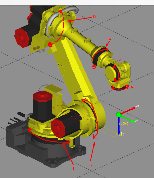
Here is a 6-axis robot (Joints highlighted) with a Cartesian absolute of [780,65,200,-180,0,90] where the parameters are [X,Y,Z,yaw,pitch,roll], in mm and deg. This is also known as Euler-Cartesian, or XYZWPR representation. most industrial robots use this. It's very rare to see Quaternion-Cartesian representation.

The absolute state of the robot in the J matrix is [0.102,-36.487,-12.657,0,-77.343,-270.102].
This is plainly, a jumbled mess, and it makes sense to use XYZWPR, as it's many times easier to visualize. For example, raising the arm by 200mm, the new $J$ matrix is [0.102,-35.138,-2.241,0,-87.759,-270.102]. You may be able to generally tell what happened, but it's not obvious at all the magnitude.
So what's the deal with these two positioning systems, and why use $J$, and not $X$? The answer is a P vs NP problem. To convert $J$ to $X$ is trivial, and does some vector addition you probably learned in secondary school. just take the angles of all of the joints, and add on the magnitude to get XYZ components, and add those components together to get a final position. Converting from $X$ to $J$ however, is a bit more advanced, and this robot for example, has up to six $J$ matrices for almost every possible $X$! Take the example above. Let's find a second $J$ associated with the $X$ above.
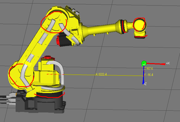
A configuration such as this:
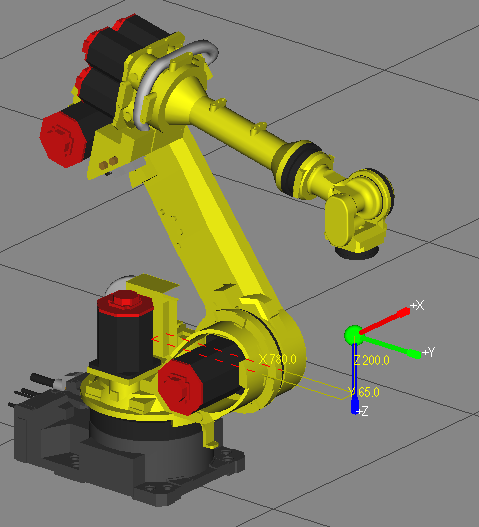
 can produce very similar results. Where the $X$ matrix is the same, the $J$ for this pose is something close to [-180, -31, 210, 180,-120,0], but $X$ is still [780,65,200,-180,0,90]. Ok. but what about an absolute match? This is actually easier than you think. Take a look at the image below. People with an astute sense of robotics may notice that the $J$ is different, but the $X$ is exactly the same!

Spot the difference yet!? The J4 axis has rotated 180 degrees! Thus the new $J$ and the old $J$ AND the alternative $J$ ALL correspond to the same $X$!
\begin{array} {|c|c|} \hline J & X \\ \hline [0.095,-36.710,-12.529,180.000,77.171,-90.195] & \downdownarrows \\ \hline [0.102,-36.487,-12.657,0.000,-77.343,-270.102] & [780,65,200,-180,0,90] \\ \hline [-180.000, -31.000, 210.000, 180.000,-120.000,0.000] & \upuparrows\\ \hline \end{array}
So in short, the pose of a robot is it's joint positions, either in absolute encoder pulses, or rotational degrees, and the state of the robot is the same thing, but including velocities (always in deg / sec. or rad / sec.). Velocity will have the same errors if the velocities are stored as XYZWPR. Some robots even include acceleration and jerk, but most do not, or store a target velocity, and acceleration and jerk limits (always joint acceleration and jerk limits, NEVER EVER Cartesian limits).