1
$\begingroup$

I am trying to spec out a motor's torque required to rotate a platform about an axis.

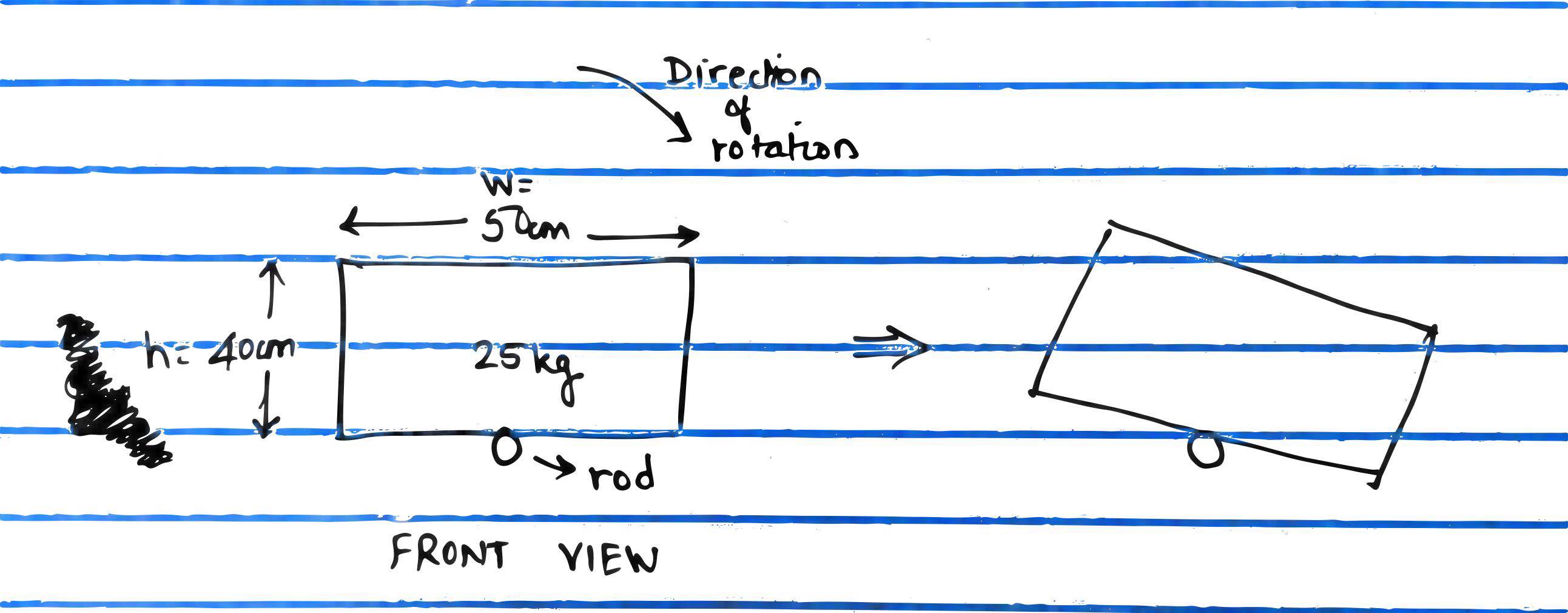
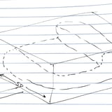
This diagram makes it better to understand(it's like a rotisserie):

Isometric view

Dimensions are in cm: Front view

I have an arbitrary shaped object on the platform that I simplified to a cuboid to calculate the moment of inertia.

The combined weight is about 25kg.

I use the moment of inertia formula for a cuboid along the length axis and use the parallel axis theorem to move the axis to where I have the rod, I get:

I = (1/2) * m * (w^2 + h^2) + m*((0.5*h)^2)
  = (1/2) * 25kg * (0.4^2+ 0.5^2) + 25 * (0.2^2)
  = 6.125 kg-m^2

Assuming I want to reach 5 rpm in 5 seconds. I have

  5rpm = (2 * pi * 5)/60  rad/s

  alpha = ((2 * pi * 5)/60 - 0)/(5-0)  rad/s^2

        = pi/30 rad/s^2

T = I * alpha = 6.125 * (pi/30) = 0.64N-m

Now I am not entirely sure if this calculation is correct. I had a 5N-m rated dc motor lying around and I fit it to the platform. The motor was able to rotate the platform about 45 degree clockwise but was not able to come back to zero degrees. Am I missing something in the above calculation? Gravity doesn't feature in my equations.

There could be other factors like friction, or the gearbox in the motor?
$\endgroup$

2 Answers 2

1
$\begingroup$

In addition to the torque required to turn, you do also need to account for the torque required to hold the load against gravity, which could be significant.

Consider your system in terms of the rod being your arm, held out in front of you, and the box being a yard brush held at the end of the handle. Starting with the brush pointing up, it requires little effort to hold in position. Similarly you can swing it through 360 degrees with only a little more effort, relying on the falling momentum to swing it back around to the top position. Now try to hold it pointing directly sideways theough. You would need to have pretty strong wrists to do that, if you can manage it at all.

Since your load is an arbitrary shape within a bounding box, I think you are better off calculating your weight distribution according to the worst case. For your system, this would be with your full 25kg load being at one of the top corners of the box.

When the rod is rotated such that the load is at its furthest extent, it is $\sqrt{40^2+(50/2)^2}\approx47.17$cm from the rod.

Calculate this torque and add it to the torque required to turn at the speed you want and you should have a motor sized for your application.

If you size your motor for worst case load, then it should should be more than adequate for any load you throw at it. If you size it for anything less, then you may find that some loads exceed the capabilities of your system, so you may need to add additional sensors or control complexity to degrade gracefully in an overload situation.

$\endgroup$
3
  • $\begingroup$ Yeah that makes sense! So we get the largest possible moment arm and assume all the weight to be concentrated there to get the max torque that would ever be required. So 25 * g * 0.4717 = 115 N-m . Now that is a huge number! $\endgroup$
    – rookie
    Commented Oct 19, 2018 at 16:43
  • $\begingroup$ What does seem interesting is that the largest moment arm would feature somewhere near 90 degrees (roughly). Wouldn't the holding torque need to be high when say the platform has moved closer to 180 degree (or a little less)? $\endgroup$
    – rookie
    Commented Oct 19, 2018 at 16:49
  • $\begingroup$ Assuming 0 degrees is top dead centre, 180 degrees would require no holding torque, as the weight would be held by the rod bearings rather than by the motor. See my explanation about why SCARA arms can be better than Articulate arms in some circumstances in my answer to Which type of actuator will be suitable for a very strong robot arm. $\endgroup$
    – Mark Booth
    Commented Oct 22, 2018 at 8:24
0
$\begingroup$

First of all, please draw the axes on the object above to make it easier for others to help you.

If you are going to rotate the cuboid from the end of the rod, you should also be using a parallel axes theorem to translate the moment of inertia equivalent to the length of the rod as well.

From my understanding, you are trying to lift the cuboid by attaching a motor at the end of the rod, am I right? This is where the clearly labeled axes are important.

$\endgroup$
1
  • $\begingroup$ Okay I changed my diagram, may be makes more sense now? $\endgroup$
    – rookie
    Commented Oct 19, 2018 at 0:52

Your Answer

By clicking “Post Your Answer”, you agree to our terms of service and acknowledge you have read our privacy policy.

Not the answer you're looking for? Browse other questions tagged or ask your own question.