The loop frequency is a parameter that needs to be tuned just like your proportional, integral, and/or derivative terms. Varying it has a similar affect on your output as varying your other parameters. Too low a frequency and you'll never reach your desired steady state. Too high and the output will oscillate.
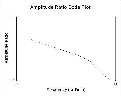
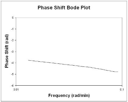
To determine the optimal loop frequency, you will first need to construct Bode plots from real world test or simulation data:
Bode plots concisely display all relevant frequency input and output
information on two plots: amplitude ratio as a functions of frequency
and phase shift as a function of frequency. The amplitude ratio plot
is a log-log plot while the phase angle plot is a semilog (or
log-linear) plot.
To construct a Bode plot, an engineer would have
empirical data showing input and output values that vary as sinusoidal
functions of time. For instance, there might be inlet temperature data
that varies sinusoidally and the outlet temperature data that also
varies sinusoidally.
The amplitude ratio, AR, is the ratio of the amplitude of the output
sinusoidal curve divided by the amplitude of the input sinusoidal
curve.
$$AR = \dfrac{outputamplitude}{inputamplitude}$$
To find the phase shift, the periods of the input and output sine
curves need to be found. Recall that the period, P, is the length of
time from one peak to the next.
$$P = \dfrac{1}{f} = \dfrac{2\pi}{\omega}$$
$$f = frequency$$
$$\omega = frequency(rad/sec)$$


Rules of Thumb when analyzing Bode plots
Generally speaking, a gain change shifts the amplitude ratio up or
down, but does not affect the phase angle. A change in the time delay
affects the phase angle, but not the amplitude ratio. For example, an
increase in the time delay makes the phase shift more negative for any
given frequency. A change in the time constant changes both the
amplitude ratio and the phase angle. For example, an increase in the
time constant will decrease the amplitude ratio and make the phase lag
more negative at any given frequency.
Then you will need to determine the cross-over frequency:
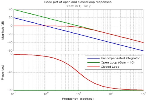
The proportional term moves the magnitude of the frequency response of
the open loop up or down and hence is used to set the cross-over
frequency of the open loop. The cross-over frequency is the frequency
at which the magnitude has a gain of 1 (or 0dB). This frequency is
important as it is closely related to bandwidth of the closed loop
response.
In an ideal system the proportional gain could be made (almost)
infinitely large leading to an infinitely fast, yet still stable,
closed loop. In practice that is not the case. Rather, two design
rules of thumb come into play.
Firstly the sample rate of the digital hardware on which the
controller is going to be executed needs to be considered. A typical
rule of thumb is that the cross-over frequency should be set to be at
least 10 times lower than the sample rate of the controller.
Conceptually this ensures that the controller is running at a fast
enough rate that it can adequately handle changes in the signal being
controlled.
The second rule of thumb is related to the slope of the frequency
response at the cross-over frequency. If the roll-off of the open-loop
magnitude response at cross-over can be made to be close to
-20dB/decade then the closed-loop bandwidth can be expected to be close to the cross-over frequency. Note that the integral and
derivative terms, not just the proportional term, are used to control
the slope at cross-over.

(emphasis mine)
So the optimal control loop frequency should be around 10 times that of the cross-over frequency of your system's phase delay which can be obtained through empirical test data or, ideally, computer simulation.


