1
$\begingroup$

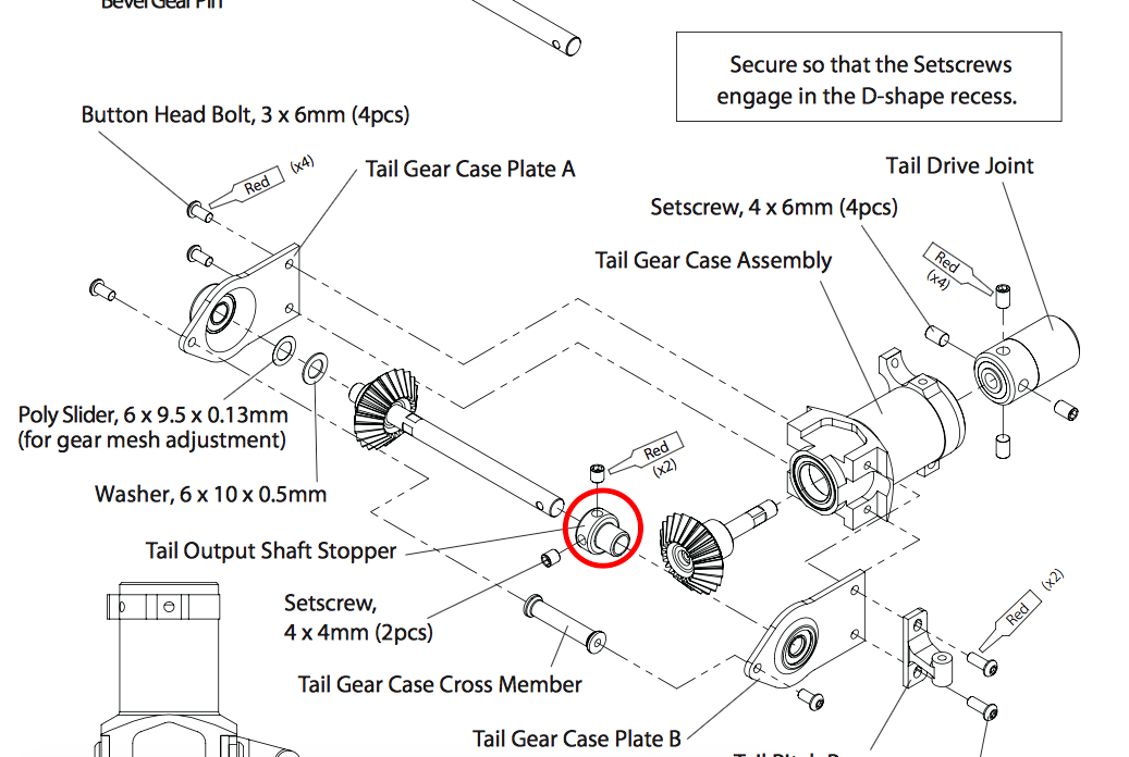
I'm looking at the assembly of a tail rotor that should look like this

enter image description here original image

I wonder if the "tail output shaft stopper" (circled in red) is meant to be a bearing or just a piece of metal stopper:

enter image description here

My reading is that, since it's held by 2 set screws, the whole part should rotate with the rod. While rotating, it'd rub against the bevel gear on the tail drive though. Am I missing something?

$\endgroup$
1
  • $\begingroup$ I voted to close this question because it's not about robotics. The general engineering site would be a better fit. For what it's worth, I think it's a clumsy attempt at a thrust bearing to retain the tail output shaft and/or set/maintain gear mesh distance, which again should be the job of a thrust bearing. $\endgroup$
    – Chuck
    Commented Feb 1, 2016 at 0:22

3 Answers 3

2
$\begingroup$

A shaft stopper like that is made to let you assemble the device more precisely. The bearings look like they are in the "Tail Gear Case Plate" subassemblies. By using a shaft stopper you can insert the shaft into the bearings, but keep the shaft stopper set screws loose. Then add whatever preload you want and locktite it in place (notice the "red" instructions in the drawing).

Regarding your additional question about how to secure the bearing: attaching a shaft and bearing can be a challenge. Often a press is used if they are smaller components. For large items the bearing is often heated, and, less commonly in my experience, the shaft may be cooled in dry ice. A press may still be needed. The tight clearance between the inner race of the bearing and the shaft helps to ensure the load is spread along the ID of the bearing.

$\endgroup$
1
  • $\begingroup$ @SteveO, as I said to TobiasK, please remember that on stack exchange, it is better to edit your answer to add information requested in comments, rather than adding more comments. Comments are for helping to improve questions and answers, and are distracting, so we try to keep them to a minimum. If all of the information needed to answer the question is contained within it, the comments can be tidied up (deleted). $\endgroup$
    – Mark Booth
    Commented Feb 1, 2016 at 9:57
1
$\begingroup$

TailRotorStopper

You can see exactly this part in your image. It won't rub anywhere. Since your second pictures shows a so called exploded drawing you cant tell a lot about exact metrics.

$\endgroup$
3
  • $\begingroup$ But what's the function of this part? Is it to prevent the output shaft from sliding out? My reading is that there's a bearing on the "Tail Gear Case Plate A", so isn't the rod somehow tightly fitted inside the bearing on that plate already? $\endgroup$
    – John M.
    Commented Jan 31, 2016 at 19:09
  • $\begingroup$ Maybe to secure the axle against displace and prevent the gearing to slip through. I'm not sure 100% $\endgroup$
    – TobiasK
    Commented Jan 31, 2016 at 21:24
  • $\begingroup$ Thanks TobiasK, I edited the question to use your image in place of the original photo. Also, remember that it is better to edit your answer to add information requested in comments, rather than adding more comments. Comments are for helping to improve questions and answers, and are distracting, so we try to keep them to a minimum. If all of the information needed to answer the question is contained within it, the comments can be tidied up (deleted). $\endgroup$
    – Mark Booth
    Commented Feb 1, 2016 at 2:43
1
$\begingroup$

As SteveO suggested, it is clear from the exploded diagram that a bearing is part of each Tail Gear Case Plate, and the Tail Output Shaft Stopper is locked to the output shaft using the set screws, which sit in the D grooves in the shaft.

The Washer and Poly Slider precisely set the distance between the left bearing and the mesh gear (actually a mitre gear), while stopping the shaft from sliding up/left on the exploded diagram and disengaging the leader and follower.

The purpose of the Tail Output Shaft Stopper is to stop the shaft being pulled in the opposite direction, which is the direction the blades are going to be causing the shaft to be pulled when rotating.

With the stopper in place, the sideways force would be applied from the shaft to the bearing, through the Stopper, with very little force applied to the mesh gear.

Without the Tail Output Shaft Stopper all of the sideways force would be applied via the mesh gear, potentially wearing it out sooner, and possibly even causing it to bind and stop rotating altogether.

This sort of arrangement is fairly common in robotics application.

$\endgroup$

Your Answer

By clicking “Post Your Answer”, you agree to our terms of service and acknowledge you have read our privacy policy.

Not the answer you're looking for? Browse other questions tagged or ask your own question.