3
$\begingroup$

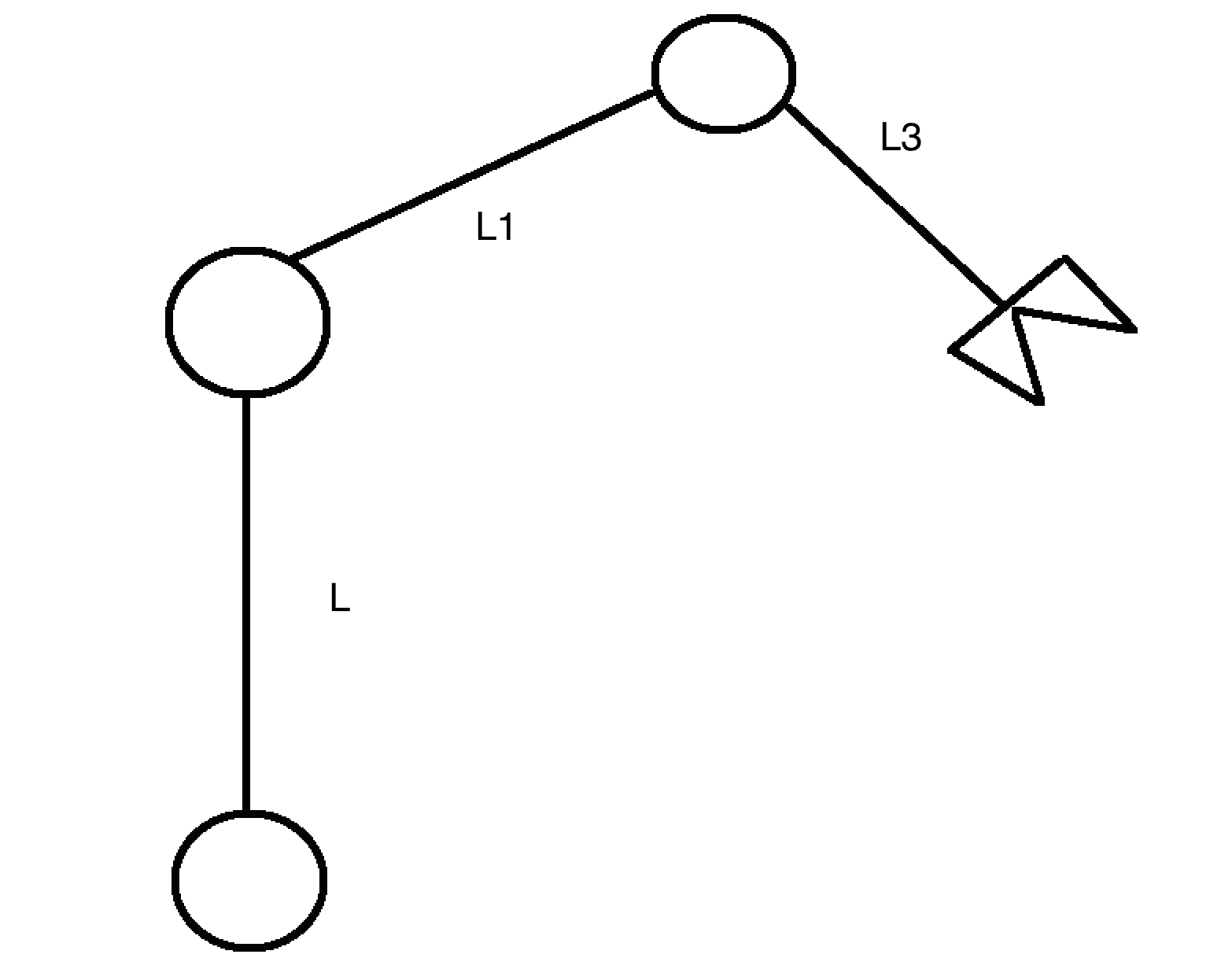
I am the moment trying to compute the transformation matrix for robot arm, that is made of 2 joints (serial robot arm), with which I am having some issues. L = 3, L1 = L2 = 2, and q = ($q_1$,$q_2$,$q_3$) = $(0 , \frac{-\Pi}{6},\frac{\Pi}{6})$

Based on this information I have to compute the forward kinematic, and calculate the position of each joint.

Problem here is though, how do I compute the angle around x,y,z.. for the transformation matrix. Using sin,cos,tan is of course possible, but what do their angle corresponds? which axis do they correspond to?

Sketch of the robot

I tried using @SteveO answer to compute the $P_0^{tool}$ using the method he provided in his answer, but I somehow mess up something, as the value doesn't resemble the answer given in the example..
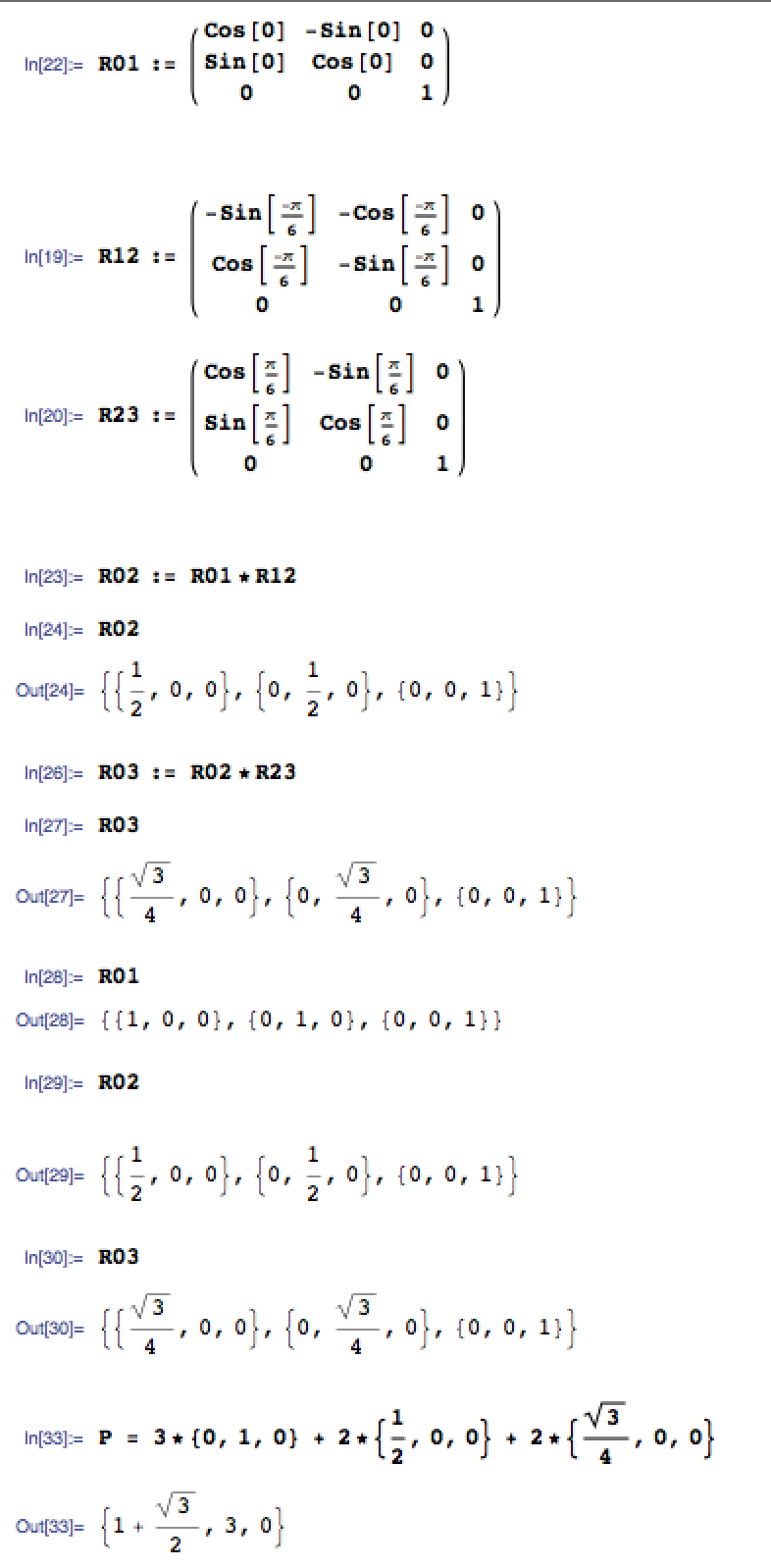
Mathmatica calculation

$\endgroup$
3
  • $\begingroup$ Why are your cosine values 0 for R02, and your sine values 0 for R03? Your final R03 matrix should have the upper left 2x2 submatrix populated with terms that include both $q_2$ and $q_3$. $\endgroup$
    – SteveO
    Commented Dec 7, 2015 at 17:04
  • $\begingroup$ If your robot is this simple, and only moves in plane...well...orientation about the X and Y axis is always 0 and rotation about the Z axis is q1+q2+q3 (but only if you defined the q motions as it generally would be in robotics, example here www2.inf.fh-brs.de/~jthoma2s/FE2Report/node40.html) $\endgroup$
    – 50k4
    Commented Dec 7, 2015 at 17:07
  • $\begingroup$ Oh, I see it. Use 'dot' for matrix multiplication. The asterisk is doing an element-wise multiplication. $\endgroup$
    – SteveO
    Commented Dec 7, 2015 at 18:28

3 Answers 3

7
$\begingroup$

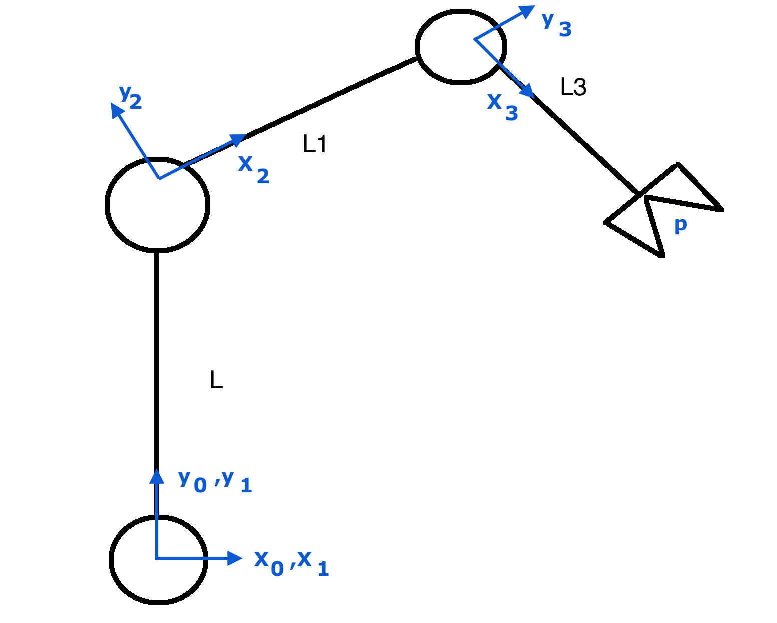
Start with coordinate systems. I've drawn one example.

Original robot with coordinate systems

In my analysis, if all $q_i = 0$ then the manipulator would point straight up. You can choose other coordinate frames to get the same result. Build your rotation matrices from the coordinate systems you set up.

The rotation matrix from coordinate system $0$ to coordinate system $1$ is $$_0^1R = \begin{bmatrix} \cos q_1&-\sin q_1&0\\ \sin q_1&\cos q_1&0\\ 0&0&1 \end{bmatrix} $$

The mapping from coordinate system $1$ to coordinate system $2$ is

$$_1^2R = \begin{bmatrix} -\sin q_2&-\cos q_2&0\\ \cos q_2&-\sin q_2&0\\ 0&0&1 \end{bmatrix} $$

And the mapping from system $2$ to $3$ is

$$_2^3R = \begin{bmatrix} \cos q_3&-\sin q_3&0\\ \sin q_3&\cos q_3&0\\ 0&0&1 \end{bmatrix} $$

Notice that all of the joint angles are taken as positive rotations around the $z$ axis. I'm not sure from your problem statement or drawing if that is your intention.

So to compute the position of point $p$ with respect to the global $0$ coordinate system, apply the vector loop

$$ \vec p = L \vec y_1 + L_1 \vec x_2 + L_3 \vec x_3$$

$\vec y_1$ is the second column from $_0^1R$. $\vec x_2$ is the first column from $_0^2R$, and $\vec x_3$ is the first column from $_0^3R$.

You compute $_0^2R$ by multiplying $_0^1R _1^2R$, and $_0^3R$ is $_0^2R _2^3R$.

$\endgroup$
9
  • $\begingroup$ Looking at this i am bit confused.. here.. So i et that you compute the rotation matrix, but why only for the Z - axis.. My understanding that the Tranformation matrix takes the rotation matrix using RPY.. ? $\endgroup$ Commented Dec 7, 2015 at 13:16
  • $\begingroup$ According to your figure, all of the links are in the same plane, with each axis of rotation coming out of the plane. I just chose coordinate systems which made all of these the $Z$ axes. When the joint axes do not align in parallel, the rotation matrices then require all three columns to be used as you work your way along the manipulator. $\endgroup$
    – SteveO
    Commented Dec 7, 2015 at 13:20
  • $\begingroup$ As this is taken from an example.. I already know the points.. It is part of an example at which I compute the jacobian.. $p^1_0$ (q) = $p^2_0$ (q) = (0, 0, 3) $p^3_0$ (q) = (1, 0, 3 + √3) ; $p^{tool}_0$ (q) = (3, 0, 3 + √3) My understanding was that to compute a forward kinematic you would need.. position and orientation of all joints which would give you a state q describing it.. $\endgroup$ Commented Dec 7, 2015 at 13:34
  • $\begingroup$ My problem is that i know the state.. and the length of each joint.. I am not sure how to retrieve the position, or the angle, thereby compute the forward kinematics. $\endgroup$ Commented Dec 7, 2015 at 13:39
  • $\begingroup$ Writing from my phone so please excuse the formatting. You can follow the answer below to get your 4x4 matrix. Alternately, you can put $_0^3R$ into the upper left 3x3, and $\vec p$ into the top three elements of the fourth column. Adding a row of 0, 0, 0, 1 will give you the forward kinematics. Can you do the vector loop equation I wrote to compute $\vec p$? $\endgroup$
    – SteveO
    Commented Dec 7, 2015 at 13:41
4
$\begingroup$

In your forward kinematics transformation matrix (4x4, incl. also translation, of just 3x3) the orientation of the end-effector is expressed relative to the base (or world) coordinate system.

SteveO described very well how to obtain the 3x3 rotation matrix, similarly you can obtain also the 4x4 transformation matrix

If you have the matrix you have to choose how do you want to express the coordinates. Commonly in robotics euler angles are used, with successive rotations about the axes of a coordinate system. After choosing the Euler angles, you also have to choose which is the succession of the rotation. In robotics in many cases the rotations are successive (intrinsic) rotations.

After choosing hwo do you want to express the orientation you can build up the orientation matrix from your rotations(e.g. X-Y-Z, then you multiply $R_{TCP} = R(\phi_x) * R(\phi_y) * R(\phi_z) $).

The orientation of your TCP expressed in function of your joints is $R_{joints}=R_{joints}(q1, q2, q3)$ or $^3_0R$ in the notation used by SteveO. Both of the matrices express the same orientation but in a different way, so $R_{TCP}=R_{joints}$ the joint angles are known in forward kinematics, so you can calculate the orientation angles. Please note that if you are using Matlab the dcm2angle() function does exactly this.

$\endgroup$
0
$\begingroup$

Try the approach used in here

The rotation matrix, using generalized coordinates, it's straightforward! Do the math and check it by trigonometry identities.

Good luck!

$\endgroup$

Your Answer

By clicking “Post Your Answer”, you agree to our terms of service and acknowledge you have read our privacy policy.

Not the answer you're looking for? Browse other questions tagged or ask your own question.