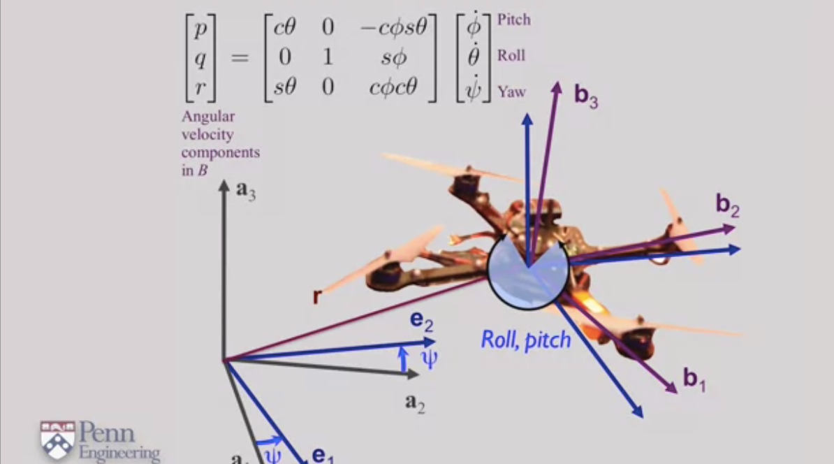
I'm following a robotics course on coursera which talks about aerial robotics and more specifically quadrotors.
I'm trying to understand the logic behind the relationship between the angular velocity expressed in the Inertial frame and the rates of change of the euler angles expressed in the body-fixed frame which are collected using an IMU sensor.
Basically in the course, the answer is given as shown below, but unfortunatly, nothing is explained.
I decided to look arround in the internet in order to understand the origin behind this inbetween matrix which converts one angular velocity to another and came up with very convenients explanations in these articles:
Wilselby Article Chrobotics Article
After understanding the idea behind this transformation matrix, which is the fact that each angular need to be reversed to a specific intermediate reference frame, which also depends on which convention we consider (Z-Y-X convention, Z-X-Y convention, ...) which is makes sense since changing the convention would mean that a specific euler angle would have a different reference frame to be reversed to afterwards.
In my course, the convention used is the Z-X-Y convention. I decided then to prove and compute the provided matrix in the course's picture with the help of Matlab. Below is the matrix i got from my Matlab program:
angularRotation =

[  cos(theta), 0, cos(phi)*sin(theta)]
[           0, 1,           -sin(phi)]
[ -sin(theta), 0, cos(phi)*cos(theta)]
You can see that the result is exactly the same as shown in the picture, except some components are in a incorrect sign.
Below is my Matlab program:
syms psi theta phi real

yaw = [cos(psi), -sin(psi), 0; sin(psi), cos(psi), 0; 0, 0, 1]
pitch = [1 0 0; 0 cos(phi) -sin(phi); 0 sin(phi) cos(phi)]
roll = [cos(theta) 0 sin(theta); 0 1 0; -sin(theta) 0 cos(theta)]

angularRotation_1 = roll * pitch * [0 0 1]' * [0 0 1]
angularRotation_2 = roll * [1 0 0]' * [1 0 0]
angularRotation_3 = [0 1 0]' * [0 1 0]

angularRotation = angularRotation_1 + angularRotation_2 + angularRotation_3
In any case the full Matlab log is needed, here it is:
yaw =

[ cos(psi), -sin(psi), 0]
[ sin(psi),  cos(psi), 0]
[        0,         0, 1]


pitch =

[ 1,        0,         0]
[ 0, cos(phi), -sin(phi)]
[ 0, sin(phi),  cos(phi)]


roll =

[  cos(theta), 0, sin(theta)]
[           0, 1,          0]
[ -sin(theta), 0, cos(theta)]


angularRotation_1 =

[ 0, 0, cos(phi)*sin(theta)]
[ 0, 0,           -sin(phi)]
[ 0, 0, cos(phi)*cos(theta)]


angularRotation_2 =

[  cos(theta), 0, 0]
[           0, 0, 0]
[ -sin(theta), 0, 0]


angularRotation_3 =

 0     0     0
 0     1     0
 0     0     0


angularRotation =

[  cos(theta), 0, cos(phi)*sin(theta)]
[           0, 1,           -sin(phi)]
[ -sin(theta), 0, cos(phi)*cos(theta)]
Thanks in advance.
