1
$\begingroup$

I have a WL v262 quadcopter and I want to control it using Arduino instead of the joysticks on the transmitter. I opened up the transmitter and saw that each joystick has 2 potentiometers on the PCB and that the voltage for each pot goes from 0-3.3V. I used arduino's PWM and a low pass filter and connected the output of the filtered output to the potentiometer's analog pin which is connected to the PCB (I cannot desolder and take out the pots from the PCB) but even with this $V_{out}$ going onto the analog pin, my transmitter's display gave ????

Now I am really confused and frustrated because I don't know how else to control this transmitter other than attaching stepper motors to the joysticks and manually controlling the transmitter but this is really my last resort. Can someone help me with this? I have spent hours and hours trial and error but I am getting nowhere.

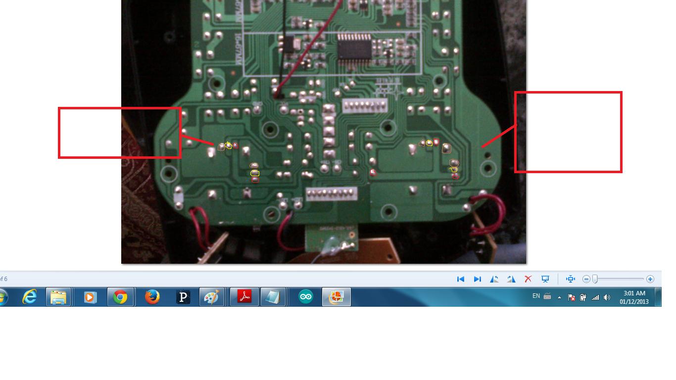
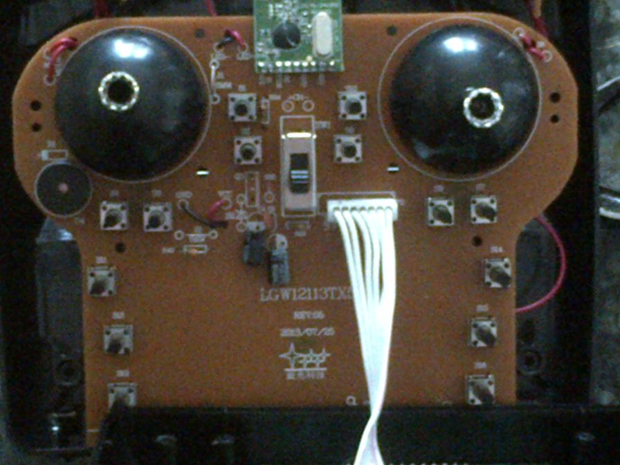
Here is the PCB of the transmitter:

enter image description here

enter image description here

$\endgroup$

4 Answers 4

1
$\begingroup$

Did it actually output only "????" Does removing the PWM restore normal operation? It is likely that the load from the PWM is not initially within correct voltage range at RC's bootup and it is detecting this and faulting. With the Pot's still inplace the range will be limited, but you could try to match it. Initially (and even while ????'ing) try to set the PWM's output to be the same voltage as when it is not connected. This may solve your ???? problem.

I also note from your picture the Transmitter module at top between joy sticks. I would suspect that you can better decipher the stream of information sent into this module by the controller and send your own information. This would be similar to what I did for IR Helicopter controllers

$\endgroup$
3
  • $\begingroup$ yes. You are right: When the transmitter is turned on, I have to move the joystick all the way at low position and move it to highest position and then back to low position. After I have done this, any movement of the joystick will start flying the quad. So maybe I can try inputting 0 V then 3.3 V then 0 V at the pot with my PWM and see if this starts it up and prevents the ????. One issue I found is that when I measure just the vout from low pass filter, I get all the values I programmed the arduino to PWM from 0-2.7 but when I PWM 3.3 V or higher, it wont go higher on pot.. $\endgroup$
    – Raynos
    Commented Dec 3, 2013 at 21:05
  • $\begingroup$ I have read online where someone uses that black chip you see on the PCB (It is apparently an encoder) to control the output that goes to the transmitter. I don't know how to do this so I am either going to keep trying this PWM method, a digital pot attempt, and as a last resort, mount servos on the transmitter to mechanically control the joysticks..I $\endgroup$
    – Raynos
    Commented Dec 3, 2013 at 21:07
  • $\begingroup$ I feel much more safe and secure with my attempts knowing that I have someone I can consult to ask and discuss about this project to get this working so thank you for the help. $\endgroup$
    – Raynos
    Commented Dec 3, 2013 at 21:10
2
$\begingroup$

Search for a Digital Potentiometer. It's exactly what you're looking for. Just replace the manual pot's with them and you can use serial connections to control the voltage.

$\endgroup$
0
$\begingroup$

The typical solution to this is not to try to inject commands into the existing remote control encoder, but rather to replace it.

Typically you start by connecting a simple USB-based logic analyzer to the signals feeding the RF submodule that is attached at the top of the board. You can do some initial identification of the lines (almost always an SPI bus, possibly with an additional enable, but very rarely a custom baud rate UART) with the analzyer's GUI interface (or a scope if available). Once you know the electrical format, you identify operations on various registers and figure out which RF chip is being used from comparison to data sheets of the likely suspects (nRF24/Beken, A7105, XN297, etc). Then you write a custom streaming decoder for the packet registers for that to plug into logic analyzer software like sigrok, so that you can move the sticks and see which parts of the transmitted packet change. And you figure out the channel hopping scheme from the writes to the channel registers.

With all of that, you have what you need to make an Arduino-like board run the RF module - or often an alternate sourced one. People have also working out how to make the nRF24L01+ talk to some similar concept chips with notably different on-air format like the X297.

It's quite likely though that you will not have to do this entire task yourself. Typically, the R/C hobby community quickly reverse engineers all of this for any interesting inexpensive toy aircraft, and creates code to the able to operate it from a hobby grade transmitter, either running the "Deviation" firmware or as a plug-in-module which takes legacy multi-channel PPM input and uses an Arduino-like MCU to encode any one of a number of toy protocols. So first do some looking on places like rcgroups for existing work on this particular toy.

In fact, the Deviation project Wiki lists the WL-v262 as using an nRF24L01-compatible radio, with what has come to be called the "V202" protocol, so likely everything you need is already available between that and the more Arduino-ish PPM translator implementation at https://github.com/pascallanger/DIY-Multiprotocol-TX-Module.
$\endgroup$
-1
$\begingroup$

I have the answer because I´ve the same problem, you can use a PWM but need use a RC low pass filter in the output http://www.avdweb.nl/arduino/hardware-interfacing/super-simple-dac.html

$\endgroup$
1
  • $\begingroup$ Welcome to robotics ivan, thanks for our answer but we prefer answers to be self contained where possible. Links tend to rot so answers which rely on a link can be rendered useless if the linked to content does rot. If you add more context from the link, it is more likely that people will find your answer useful. $\endgroup$
    – Mark Booth
    Commented Mar 27, 2015 at 17:06

Your Answer

By clicking “Post Your Answer”, you agree to our terms of service and acknowledge you have read our privacy policy.

Not the answer you're looking for? Browse other questions tagged or ask your own question.