5
$\begingroup$

I am really struggling to understand how to do Cartesian velocity control when 3D rotations are involved. So, below is a very simple example which I am hoping somebody can help me with.

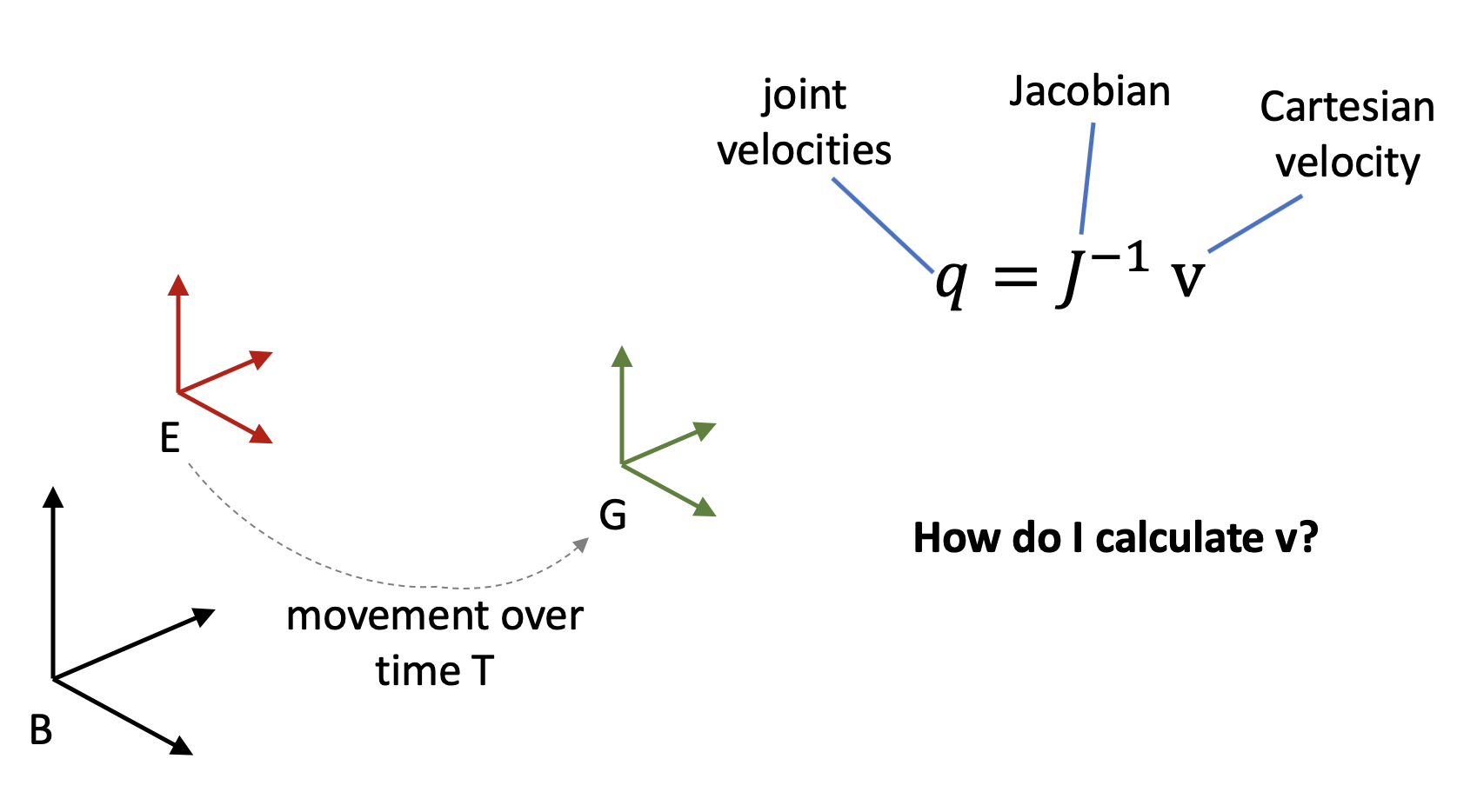
Let's say the base frame of my robot is labelled $B$, the end-effector frame is labelled $E$, and the goal frame is labelled $G$. So, the Cartesian pose of the end-effector relative to the base can be expressed as a matrix $T_{BE}$, and similarly, $T_{BG}$ for the goal. The Jacobian, which describes the rate of change of the end-effector about the base frame, is $J$.

I want to move the end-effector from $E$ to $G$, in time $T$. To do this, I can create a loop which continually calculates the required Cartesian velocity of the end-effector, about the base frame. This is a vector length 6, containing translational velocity about the base's x-y-z axes, and rotational velocity about the base's x-y-z axes. We call this velocity vector $v$. Then, I will move the end-effector at this velocity, using the inverse Jacobian to calculate the required velocities of the joints, $q$. This equation is $q = J^{-1} v$.

However, what I don't understand, is how to calculate $v$, which is the required Cartesian velocity of the end-effector about the base frame. I know how to do this with 1D rotation: I would just take the difference between the current angle and the goal angle, and divide by $T$. I also know how to do this in 3D if the motion only involves translation, and no rotation: again, I can find the difference in the current and goal position. But when 3D rotations are involved, I don't know how to do this.

I have tried converting matrices $T_{BE}$ and $T_{BG}$ into Euler representations (with X-Y-Z rotations about $B$), and then finding the difference in the three components of the Euler vectors, between $T_{BE}$ and $T_{BG}$. My intuition was that I could then divide these three components by $T$, and this would give me the rotational velocity components of vector $v$. However, I have implemented this, and I do not get the desired behaviour. I think that this is because the three rotational components are dependent on each other, and so I cannot simply treat each one independently like this.

So, can anybody help me please? How can I create the rotational components of vector $v$, given the current pose $T_{BE}$ and the target pose $T_{BG}$?

The below image summarises the problem:
enter image description here

$\endgroup$

2 Answers 2

8
$\begingroup$

You essentially want to find the time derivative of a linear interpolation between two rotations. The easiest way to obtain this would probably to convert the rotation matrix between the two orientations to a axis-angle representation and the angular velocity would simply be the axis times the angle divided by $T$.

$\endgroup$
4
  • $\begingroup$ Hi fibonatic, thanks for your answer. That makes sense to me. But another idea would be to take the Euler angle representations of the two orientations, and find the difference between them. Would this give the same effect as your idea? $\endgroup$ Commented Jul 14, 2020 at 10:05
  • 1
    $\begingroup$ @JohnRowlay linearly interpolating Euler angles do in general not give a constant rate of rotation, while the method I described does. It can also be noted that my method is in most cases also equivalent to using Quaternion Slerp. $\endgroup$
    – fibonatic
    Commented Jul 14, 2020 at 16:05
  • $\begingroup$ Thanks, I think I understand this a bit better now. Just one more thing though. Let's say I calculated $v$ by taking the difference in the two Euler angles, and dividing by time $T$. Even if the rotation would not necessarily be smooth, would the end-effector arrive at $G$ after time $T$? Or would it actually move to a different pose? The reason I am confused here is that Euler rotations involve three sequential rotations, but the vector $v$ applies a rotation about all three axes instantaneously. So I don't know whether this instantaneous rotation would arrive at $G$. $\endgroup$ Commented Jul 14, 2020 at 16:26
  • 1
    $\begingroup$ @JohnRowlay You can derive the angular velocity associated with the linear interpolation of Euler angles. However, due to the way a rotation using Euler angles is defined would cause this angular velocity to change with time. Where as with the method from my answer the angular velocity would be constant. $\endgroup$
    – fibonatic
    Commented Jul 14, 2020 at 17:56
0
$\begingroup$

You could run the solution with some guess of $v$ then command a velocity normalized by how long your guess velocity took.

$\endgroup$

Your Answer

By clicking “Post Your Answer”, you agree to our terms of service and acknowledge you have read our privacy policy.

Not the answer you're looking for? Browse other questions tagged or ask your own question.