That is a very good choice since DVD motor operate under 2A.
I'm using the very same driver to manage my DVD drivers also NEMA23.
You just need to take care about trimming the current limit very well and concern about chinese production because they differ between resistors. Note that the original StepStick stepper driver boards use 0.2 Ohm current sense resistors (Rs) while the original Pololu A4988 stepper driver boards uses 0.05 Ohm current sense resistors. However, the Made in China A4988 stepper driver boards use various current sense resistors depending on the manufacturer (usually either 0.05 Ohm, 0.1 Ohm or 0.2 Ohm). The current sense resistors are the two small black components next to the main chip. Compare the pictures above and check the detail below: the green Made in China A4988 board was fit with 0.1 Ohm resistors (labeled with "R100") while the red StepStick Made in China clone was fit with 0.2 Ohm resistors (labeled with "R200"), while other Made in China A4988 boards may come with 0.05 Ohm (labeled with "R050") current sense resistors. So it is very important that you closely examine your stepper driver boards and use the exact values for the current sense resistors when calculating the Vref formula (see an example below).
A4988 Resistor

Tuning motor current:
Per the A4988 datasheet, the calculation for the maximum trip current is:
I_TripMax= Vref/(8*Rs)
With Pololus, the sensing resistors are Rs=0.05 ohm, so a Vref of 0.4 should produce a maximum current of 0.4/(8*0.05)=1A. Clockwise increases the current which will make the motor run hotter and counterclockwise reduces it which will cool it down (see forum thread 159081).
As another example, aiming for 50% temperature rise on 1A rated steppers by using max 0.7A, so rearrange it as:
Vref = I_TripMax * 8 * Rs
or
Vref = 0.7A * 8 * 0.05 = 0.280V
With a measured Vref of 0.273V, I should expect 0.6825A, and I measured the current through one coil as 0.486A in full step mode, which should be 0.7071 of the full trip current, or I_TripMax= 0.486/0.7071= 0.687A, which seems close enough.
The Vref signal is accessible as the "VREF" pin on the carriers with voltage regulators, as the through-hole via on the carriers without, and also as the wiper on the trim pot itself on both carriers.
example of a v-ref checking, + probe on the turnpot and - on a ground pin
Note 1: for StepStick, the Rs=0.2 ohm, so you'd get 4 times the Vref at the same current.
Note 2: most "Made in China" A4988 Pololu knock-offs have Rs=0.1 ohm
Example of a v-ref checking, + probe on the turnpot and - on a ground pin

How to wire and control your stpper motor:
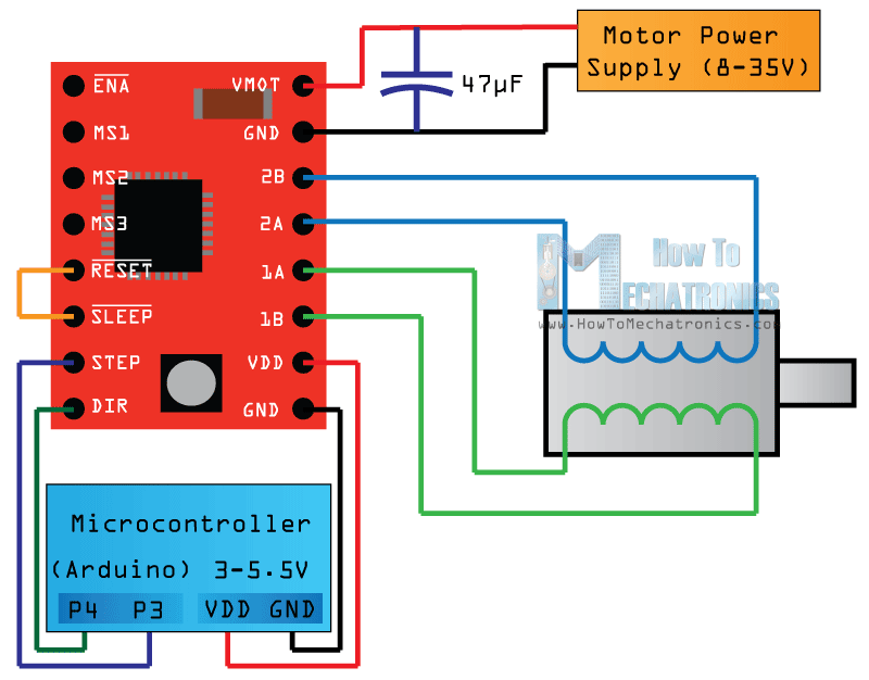
Start with the 2 pins on the botton right side for powering the driver, the VDD and Ground pins that we need to connect them to a power supply of 3 to 5.5 V and in your case that will come from your controller, the Arduino Board which will provide 5 V. The following 4 pins are for connecting the motor. The 1A and 1B pins will be connected to one coil of the motor and the 2A and 2B pins to the other coil of the motor.

The next two 2 pins, Step and Direction are the pins that we actually use for controlling the motor movements. The Direction pin controls the rotation direction of the motor and we need to connect it to one of the digital pins on our microcontroller, or in our case I will connect it to the pin number 4 of my Arduino Board. With the Step pin we control the mirosteps of the motor and with each pulse sent to this pin the motor moves one step. So that means that we don’t need any complex programming, phase sequence tables, frequency control lines and so on, because the built-in translator of the A4988 Driver takes care of everything. Here we also need to mention that these 2 pins are not pulled to any voltage internally, so we should not leave them floating in our program.
Next is the SLEEP Pin and a logic low puts the board in sleep mode for minimizing power consumption when the motor is not in use.
Next, the RESET pin sets the translator to a predefined Home state. This Home state or Home Microstep Position can be seen from these Figures from the A4988 Datasheet. So these are the initial positions from where the motor starts and they are different depending on the microstep resolution. If the input state to this pin is a logic low all the STEP inputs will be ignored. The Reset pin is a floating pin so if we don’t have intention of controlling it with in our program we need to connect it to the SLEEP pin in order to bring it high and enable the board.
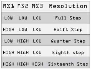
The next 3 pins (MS1, MS2 and MS3) are for selecting one of the five step resolutions according to the above truth table. These pins have internal pull-down resistors so if we leave them disconnected, the board will operate in full step mode.

Don't forget
The only thing you need to real concern is if your motor is Unipolar or Bipolar. A4988 are designed to control bipolar stepper motors, but you can set your Unipolar motor as Bipolar.
To make sure about your stepper motor, just look for his datasheet using his product number or model number on Google. If you can't find this, please look how to wire your stepper motor using the following links as source:
http://www.linengineering.com/resources/wiring-connections/
http://reprap.org/wiki/Stepper_wiring
http://digital.ni.com/public.nsf/allkb/B1CC4C64ABBC7D3C86257BC70017B9E2


