1
$\begingroup$

I bought a little toy helicopter, namely the Revell Control 23982. After flying a few batteries I was wondering whether I could hack it in such a way, that my Arduino Uno can control/manipulate the signals from the transmitter to the receiver on board. However, to me it seems like I have big trouble getting started on the right path. Can anyone spot out my mistakes?

Hardware hack

My first attempt was to bridge the potentiometers in the transmitter with the Arduino, this did not work at all. I think this is because the Arduino is using PWM and no true DC. Also I do not understand how the potentiometer (shown in the picture) works, where two of the three terminals are connected to each other.
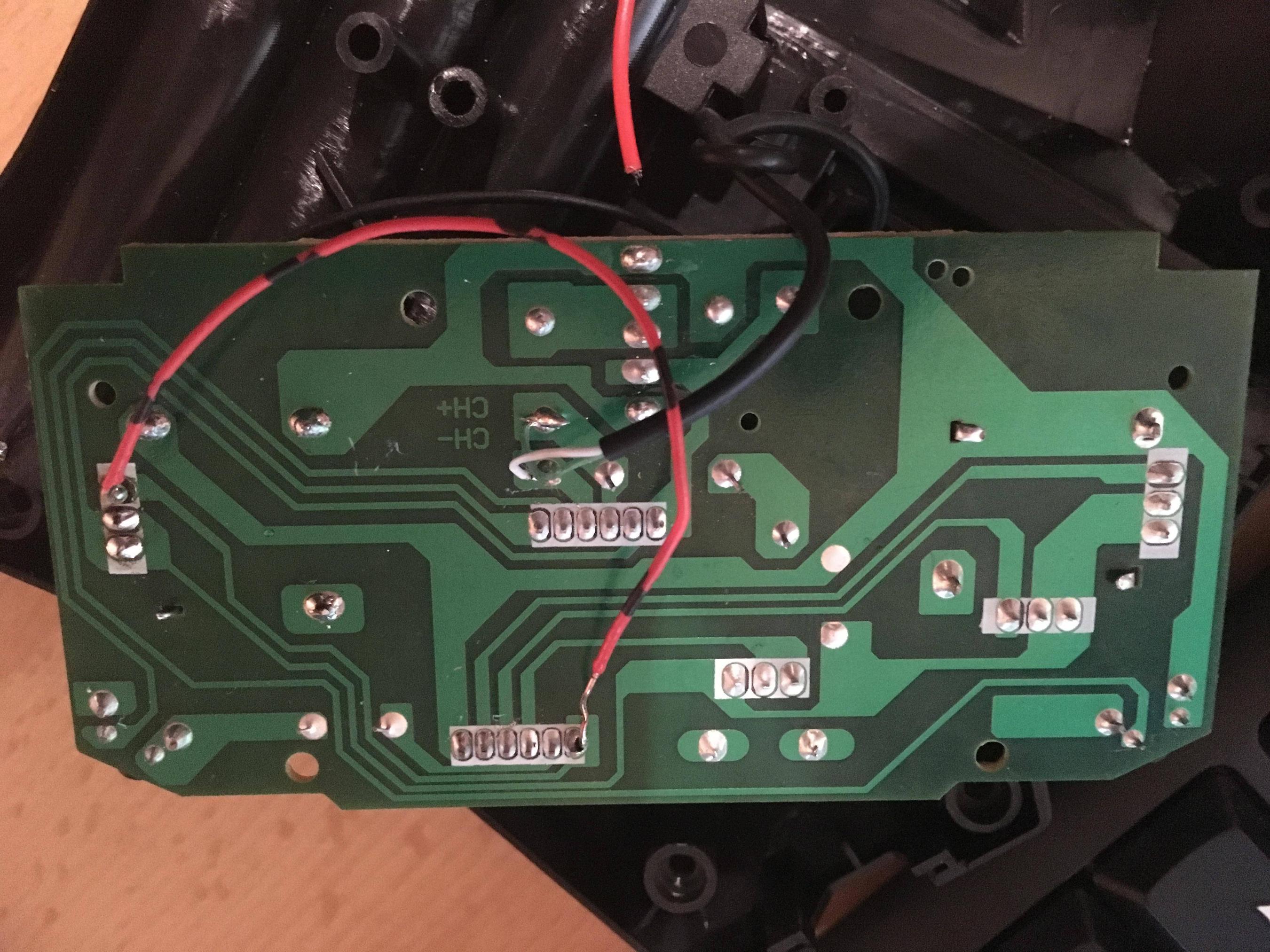
Bottom side of PCB
NOTE: The soldered cable is a result of some unsuccessful hardware soldering.

EDIT

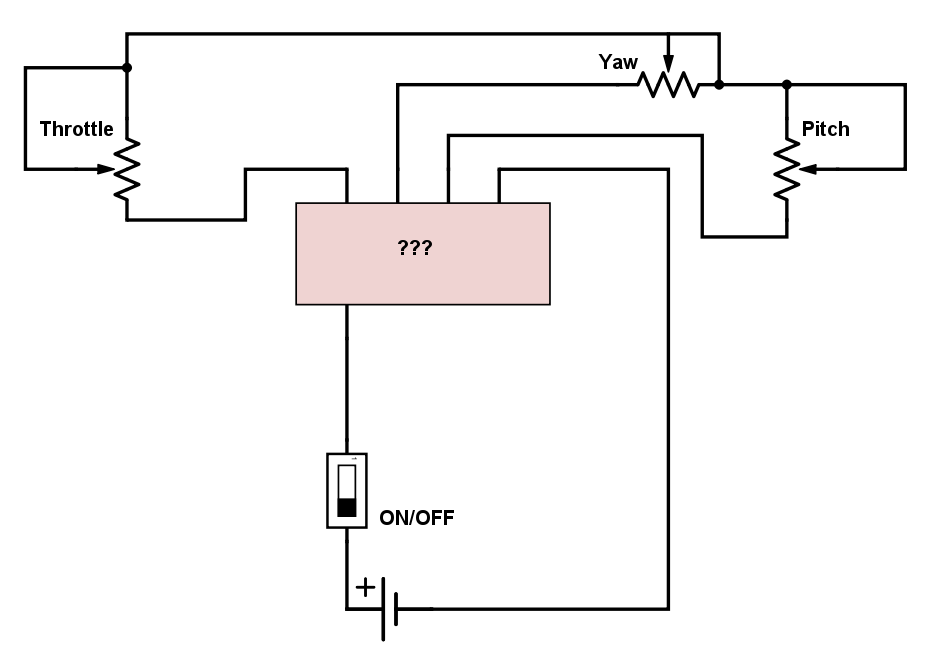
Here is further information according to @combos comment.

Excerpt

NOTE: The diagram is missing a connection between the line that connects all potentiometers and a 3v pin on the IC. Sorry for that.

This is a simple excerpt of the actual PCB, however, it should be the one which is important for my question. It is true that two terminals of the potentiometers are connected, and all the potentiometers are additionally soldered to ground via their housing. I was not able to find any information about the IC labelled "???". It contains the transmitter, that is clear.

A test with my multi-meter showed, that there is a maximum current flow of three volts on the single line of each potentiometer, and the connection between all of them is 3v consistent.

Software hack

My second attempt was trying to reverse engineer the 2.4GHz transmission via an nrf24l01 module, as some other people on the internet have been successful doing this with some other toys. I tried to scan the frequency bands, however with no successful outcome. I have no clue which transmitter module is being used on the board.

TL;/DR;

My questions:

  • Is it even possible to achieve what I want?
  • If yes, what do I need to do?
  • If not, what did others do to achieve this kind of behaviour?
  • Which circuit do I need to convert digital PWM in analog?

If you need any additional information please let me know!
$\endgroup$
9
  • $\begingroup$ Yes I think replacing the remote with an arduino is possible, but I think you have some legwork to do. I would start by drawing out a schematic of the remote control - it is a single-layer board so it should be pretty straightforward. Use a multimeter to get resistance/voltage values (especially for the potentiometers). You can use PWM to replace a potentiometer, but you will want to use a capacitor to convert the digital signal into an analog one, and be sure to match the voltages which the potentiometer on the board gives. If you post the schematic then we can give more specific advice :) $\endgroup$
    – combo
    Commented Feb 28, 2017 at 17:26
  • $\begingroup$ @combo Thank you for your answer, I edited my question according to your recommendation. Hope you can help me more now! $\endgroup$
    – Teecup
    Commented Mar 1, 2017 at 14:23
  • $\begingroup$ That's helpful! You have maximum voltages, the last pieces of the puzzle is to figure out whether you have an exponential or linear response, what the minimum value is, and whether the circuit cares about voltage or resistance. Then you could either use a pwm driven system or a digital potentiometer. Note that you will need to disconnect the current potentiometers, the simplest/least damaging way is probably to use a knife to cut the 3V lines to each of the potentiometers. $\endgroup$
    – combo
    Commented Mar 1, 2017 at 16:25
  • $\begingroup$ Also since your RC controller is 3V, it's a good idea to use a 3V microcontroller (most arduinos are 5V). $\endgroup$
    – combo
    Commented Mar 1, 2017 at 16:27
  • $\begingroup$ Thank you for your fast response! Could you explain to me where the PWM driven system needs to be connected? Wouldn't be desoldering the current potentiometers enough? $\endgroup$
    – Teecup
    Commented Mar 1, 2017 at 16:30

2 Answers 2

0
$\begingroup$

I guess this uses PWM (from what I understand from the question's description). Almost all standard flight-controllers use PWM values ranging from 1000 microseconds to 2000 microseconds refreshed at 50 Hz. Regarding potentiometer, it is used to control voltage (and some people do use it to drive current; But, it has drawbacks which I'll discuss later). The Vin and the ground are the top and bottom pins while a potential divider circuit creates a potential (w.r.t ground) which is proportional to the variable resistance between Vout and ground while total resistance of both resistances remains same due to resistance strip. More info on Wikipedia: https://en.wikipedia.org/wiki/Potentiometer#Theory_of_operation and http://lmgtfy.com/?q=potentiometer .

Regarding the potentiometer, it is used because it is intuitive for us to use; We just use potentiometer angle as a measure of proportional linear actuation metric. (instead of 1 millisecond to 2 millisecond PWM train of 20 milliseconds as in standard OverrideRC methods which are counter-intuitive http://answers.ros.org/question/197109/how-does-mavros-rc-override-work/) You can connect potentiometer to arduino or so and then use PWM as output of Arduino and input of flight controller. But, if you use this to drive current, then, the potential divider calculations must be done for three resistors including the load resistance and thus, this resistance in parallel causes a non-linear relation with the input potentiometer angle.

I would have probably answered better if I were to have known both sides of the PCB as I could not gather much info online apart from some vague description like this one on Amazon. +1 for the hack and attempt.

$\endgroup$
-1
$\begingroup$

As @combo pointed out, the solution to my problem was that the potentiometers are driving current rather than voltage! I just connected another one in parallel and the hack was done. Thanks!

$\endgroup$
1
  • $\begingroup$ Welcome to Robotics Teecup. While we are happy for people to answer their own questions, we are looking for comprehensive answers that provide some explanation and context. One or two line answers cannot do this, so please edit your answer to explain why it is right, ideally with citations. Also, since comments may be deleted at any time, answers which rely on the contents of comments could easily become useless, so please edit your answer to include all relevant information from combo's comments. $\endgroup$
    – Mark Booth
    Commented May 1, 2017 at 9:59

Your Answer

By clicking “Post Your Answer”, you agree to our terms of service and acknowledge you have read our privacy policy.

Not the answer you're looking for? Browse other questions tagged or ask your own question.