4
$\begingroup$

I am trying to implement quaternions and i am using CC2650 sensortag board from TI. This board has MPU9250 from invensense which has Digital Motion Processor (DMP) in it. This DMP gives quaternion, but for my understanding i implemented my own quaternion. I used Gyroscope and acceleorometer values coming out of DMP (which are calibrated ) to calculate angle of rotation. I feed this angle, in 3 directions (x,y,z), to my quaternion. I am not able to match my quaternion values with DMP quaternion values. In fact it's way off, so wondering what I have done wrong.

Following are detailed steps that i did :

1) Tapped Gyro sensor values from function “read_from_mpl”.

2) Converted gyro values in to float by diving by 2^16. As gyro values are in Q16 format.

3) Now used Gyro values of 3 axis and found out resultant using formula : Gr = sqrt(Gx^2+Gy^2+Gz^2) Where Gx,Gy and Gz are Gyro values along x-axis,y-axis and z-axis respectively.

4) Now Angle is derived using above found resultant Gr by : *Angle = Gr*1/sample_rate* Where sample_rate is found using API call ,mpu_get_sample_rate(&sample_rate)

5) This Angle is fed to angle_to_quater function which basically converts angle to axis and then quaternion multiplication.

/* Angle to axis and quaternion multiplication: */
temp.w = cos((Angle*1.0/RAD_TO_DEG)/2);
temp.x = sin((Angle*1.0/RAD_TO_DEG)/2);
temp.y = sin((Angle*1.0/RAD_TO_DEG)/2);
temp.z = sin((Angle*1.0/RAD_TO_DEG)/2);
temp.x = temp.x *gyro_axis[0];//gyro_axis[0]=Gx
temp.y = temp.x *gyro_axis[1]; //gyro_axis[0]=Gy
temp.z = temp.x *gyro_axis[2]; //gyro_axis[0]=Gz
/* quaternion multiplication and normalization */
res = quat_mul(*qt,temp);
quat_normalize(&res);
*qt = res;*   

6) I also added doing angle calculations from accelerometer as follows : Here also accelerometer is converted to float by dividing by 2^16, as acceleorometer values also in Q16 format.

*//acc_data[0]->Ax, acc_data[1]->Ay, acc_data[2]->Az
temp = (acc_data[0]*acc_data[0]) + (acc_data[1]*acc_data[1]);
acc_angle[0]=atan2(acc_data[2],temp)*RAD_TO_DEG;
temp = (acc_data[1]*acc_data[1]) + (acc_data[2]*acc_data[2]);
acc_angle[1]=atan2(acc_data[0],temp)*RAD_TO_DEG;
temp = (acc_data[1]*acc_data[1]) + (acc_data[0]*acc_data[0]);
acc_angle[2]=atan2(acc_data[1],temp)*RAD_TO_DEG;*

*Find resultant angle of this also as :

inst_acc_angle = (sqrt(acc_angle[0]*acc_angle[0] + acc_angle[1]*acc_angle[1] + acc_angle[2]*acc_angle[2]));*

7) Then complimentary filter is : *FinalAngle = 0.96*Angle + 0.04*inst_acc_angle; This Final Angle is fed to step 5 to get quaternion.*

Quaternion multiplication is done as below and then normailized to get new quaternion (q).

quater_mul :

q3.w = -q1.x * q2.x - q1.y * q2.y - q1.z * q2.z + q1.w * q2.w;
q3.x =  q1.x * q2.w + q1.y * q2.z - q1.z * q2.y + q1.w * q2.x;
q3.y = -q1.x * q2.z + q1.y * q2.w + q1.z * q2.x + q1.w * q2.y;
q3.z =  q1.x * q2.y - q1.y * q2.x + q1.z * q2.w + q1.w * q2.z;

quat_normalize:

double mag = pow(q->w,2) + pow(q->x,2) + pow(q->y,2) + pow(q->z,2);
mag = sqrt(mag);
q->w = q->w/mag;
q->x = q->x/mag;
q->y = q->y/mag;
q->z = q->z/mag;

When i check my quaternion values with DMP, they are WAY off. Can you please provide some insights in to what could be wrong here.

Source code :

acc_data[0]=data[0]/65536.0;
acc_data[1]=data[1]/65536.0;
acc_data[2]=data[2]/65536.0;
double temp = (acc_data[0]*acc_data[0]) + (acc_data[1]*acc_data[1]);
acc_angle[0]=atan2(acc_data[2],temp)*RAD_TO_DEG;
temp = (acc_data[1]*acc_data[1]) + (acc_data[2]*acc_data[2]);
acc_angle[1]=atan2(acc_data[0],temp)*RAD_TO_DEG;
temp = (acc_data[1]*acc_data[1]) + (acc_data[0]*acc_data[0]);
acc_angle[2]=atan2(acc_data[1],temp)*RAD_TO_DEG;*

gyro_rate_data[0]=data[0]/65536.0;
gyro_rate_data[1]=data[1]/65536.0;
gyro_rate_data[2]=data[2]/65536.0;

float inst_angle = (sqrt(gyro_rate_data[0]*gyro_rate_data[0] +  gyro_rate_data[1]*gyro_rate_data[1] + gyro_rate_data[2]*gyro_rate_data[2]));
gyro_rate_data[0] = gyro_rate_data[0]/inst_angle;
gyro_rate_data[1] = gyro_rate_data[1]/inst_angle;
gyro_rate_data[2] = gyro_rate_data[2]/inst_angle;
inst_angle = inst_angle *1.0/sam_rate;
float inst_acc_angle = (sqrt(acc_angle[0]*acc_angle[0] + acc_angle[1]*acc_angle[1] + acc_angle[2]*acc_angle[2]));
inst_angle = WT*inst_angle + (1.0-WT)*inst_acc_angle;

angle_to_quat(inst_angle,gyro_rate_data,&q);

/* The function for angle to quaterinion and multiplication,normalization */
void angle_to_quat(float Angle,float *gyro_axis,struct quat *qt)
{
    struct quat temp;
    struct quat res;
    temp.w = cos((Angle*1.0/RAD_TO_DEG)/2);
    temp.x = sin((Angle*1.0/RAD_TO_DEG)/2);
    temp.y = sin((Angle*1.0/RAD_TO_DEG)/2);
    temp.z = sin((Angle*1.0/RAD_TO_DEG)/2);
    temp.x = temp.x *gyro_axis[0];
    temp.y = temp.x *gyro_axis[1];
    temp.z = temp.x *gyro_axis[2];
    res = quat_mul(*qt,temp);
    quat_normalize(&res);
    *qt = res;
}

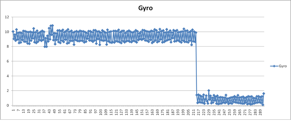
enter image description here

This variation is coming when i am keeping my device stationary.

Y-Axis : Resultant of all 3 gyro axis.

X-axis : The number of samples. (have not converted them to time)

Sample_rate is 3Hz.
$\endgroup$
6
  • 1
    $\begingroup$ Could you please check and fix the formatting of your code? $\endgroup$ Commented Jul 25, 2016 at 10:36
  • $\begingroup$ I have tried to tidy up your code @Vinay but in future, please use the code insert tool {} to format your code. Also, on Robotics we are fortunate enough to have MathJax support enabled, allowing you to easily create subscripts, superscripts, fractions, square roots, greek letters and more. This allows you to add both inline and block element mathematical expressions in robotics questions and answers. For a quick tutorial, take a look at How can I format mathematical expressions here, using MathJax? $\endgroup$
    – Mark Booth
    Commented Jul 28, 2016 at 11:05
  • $\begingroup$ If you can confirm that the code as it now stands is correct, I will happily re-open this question. $\endgroup$
    – Mark Booth
    Commented Jul 28, 2016 at 11:06
  • $\begingroup$ Also, you say "When i check my quaternion values with DMP, they are WAY off.", so it would be a good idea to give us a table with example input values, the output values calculated from them, and what you expected those outputs to be. We don't know what input values you are using, so they may help us understand what makes the outputs WAY off. $\endgroup$
    – Mark Booth
    Commented Jul 28, 2016 at 11:11
  • $\begingroup$ Yes Mark. The code is correct . Rather than comparison with DMP results, what i see is my Gyro values are as shown in graph.(i will try to add this behaviour of gyro). Just for a note , in case you look for what is WT, its value is 0.96. $\endgroup$
    – Vinay
    Commented Jul 29, 2016 at 6:03

1 Answer 1

3
$\begingroup$

So, as I mentioned in an earlier comment, it looks like you're using a mashup of methods. You're not applying any one method correctly; instead you're mis-using part of one method, then using the results of that to another mis-applied half-method, and so on.

First, maybe a refresher on rotation matrices. You can rotate about each of the three primary axes - the x-axis ($\phi$ or "roll"), the y-axis ($\theta$ or "pitch"), and the z-axis ($\psi$ or "yaw").

The order in which you do these operations matters - if you pitch then yaw, that gives you a different orientation than if you yaw then pitch. Try with your hand and see, and remember that each rotation happens about the hand's orientation axes, not global axes.

For each rotation, you multiply the rotation matrices together. Conceptually, this is representing a set of successive rotations. For example, if you have:

$$ \mbox{output} = R(\psi)R(\theta)R(\phi) \mbox{input} \\ $$ then you can see that this is equivalent to: $$ \mbox{intermediate}_{\phi} = R(\phi)\mbox{input} \\ \mbox{intermediate}_{\theta} = R(\theta)\mbox{intermediate}_{\phi} \\ \mbox{output} = R(\psi)\mbox{intermediate}_{\theta} \\ $$

This explicitly shows successive rotations, but you can also "collapse" the rotation matrices into one "shortcut" rotation matrix -

$$ R(\mbox{net}) = R(\psi)R(\theta)R(\phi) \\ \mbox{output} = R(\mbox{net})\mbox{input} \\ $$

First portion of your code.

That mentioned, take a look at the beginning of your code. I think the MathJax is easier to look at than code, so I'll use that. First, you get the accelerometer data and then "convert to angles" as follows:

$$ \phi_x = \tan^{-1}{\left(\frac{a_z}{a_x^2 + a_y^2}\right)} \\ \theta_y = \tan^{-1}{\left(\frac{a_x}{a_y^2 + a_z^2}\right)} \\ \psi_z = \tan^{-1}{\left(\frac{a_y}{a_y^2 + a_x^2}\right)} \\ $$

First thing to note about this is that generally you have one axis divided by the other two, except for the last line - there you have y/(y^2+x^2), which breaks your pattern.

Second thing to note about this is that it seems like maybe you're trying to use the same method given in this application note from Freescale Semiconductor (Document Number: AN3461) that says (briefly, from Page 10):

Solving for the roll and pitch angles... and using the subscript xyz to denote that the roll and pitch angles are computed according to the rotation sequence $R_{xyz}$, gives:

$$ \tan{\phi}_{xyz} = \left(\frac{G_{py}}{G_{pz}}\right) \\ \tan{\theta}_{xyz} = \frac{-G_{px}}{\sqrt{G_{py}^2 + G_{pz}^2}} \\ $$

Solving for the roll and pitch angles... and using the subscript yxz to denote that the angles are computed according to the rotation sequence $R_{yxz}$, gives:

$$ \tan{\phi}_{xyz} = \frac{G_{py}}{\sqrt{G_{px}^2 + G_{pz}^2}} \\ \tan{\theta}_{xyz} = \left(\frac{-G_{px}}{G_{pz}}\right) \\ $$

The document also states (bottom of Page 9) that isn't not possible to get yaw angle without a compass. So, hopefully at this point you can begin to see what I'm calling a "misapplied mashup":

  1. Your method uses $\tan^{-1}\left(a/(b^2 + c^2)\right)$ for each angle. This is missing a square root symbol in the denominator.
  2. More importantly, if you use that form for roll and pitch angles, then you're getting roll from one rotation sequence and pitch from a different rotation sequence.
  3. Also, the sign on that form should change.
  4. Regardless of points 1-3 above, you cannot use this method for yaw angle.

Second portion of your code.

Now we move on from here to the gyro section. Remember that a gyroscope outputs angular velocities. It looks like you calculate the "rotational velocity magnitude" as:

$$ \mbox{inst_angle} = \sqrt{\omega_x^2 + \omega_y^2 + \omega_z^2} \\ $$

And then you calculate an "axis" as:

$$ \mbox{x-axis component} = \frac{\omega_x}{\mbox{inst_angle}} \\ \mbox{y-axis component} = \frac{\omega_y}{\mbox{inst_angle}} \\ \mbox{z-axis component} = \frac{\omega_z}{\mbox{inst_angle}} \\ $$

This seems to work out, except you calculate the incremental angle that you use to rotate about this axis:

$$ \mbox{inst_angle} = \mbox{inst_angle}/\mbox{sample rate} \\ $$ which, for the record, is equivalent to: $$ \mbox{inst_angle} = \mbox{inst_angle} * \mbox{sample period} \\ $$

At this point, you get the "mis-applied" portion of the gyro code. The accelerometer-angle equations from the first section should give absolute angles (based on whichever rotation sequence you choose to use*. The gyro-angle equation above gives you an incremental angle. Further, the gyro-angle is the incremental rotation about the axis you calculate, where the accelerometer-angle is the absolute angle relative to the world frame.

However, even though these are different angles (incremental vs. absolute), and even though they're in different frames (about an axis vs. relative to world frame), you proceed to push the two together by smooshing the accelerometer-angles into a "magnitude" (which doesn't make sense) and then add them with a complementary filter:

$$ \mbox{inst_accel_angle} = \sqrt{\phi_x^2 + \theta_y^2 + \psi_z^2} \\ \mbox{inst_angle} = \alpha \left(\mbox{inst_angle}\right) + (1-\alpha)\left(\mbox{inst_accel_angle}\right) \\ $$

Final portion of your code:

At this point, you have an "angle" and an "axis", and it looks like you correctly convert the axis/angle set to a quaternion, however, this quaternion is more of an incremental quaternion because the axis is based off of rate (angular velocity) information. The angle is a mash-up of incremental and absolute angles, so it doesn't mean much of anything.

Consider this - if you actively move the sensor to a new orientation, your quaternion will change to some non-zero axis while you're moving it because the axis is based on your angular velocity. When you hold it stead at the new orientation, even though it's pointed in some direction your axis information is now zero because your rate is zero.

The solution

Remember that a quaternion represents an orientation, so let's leave out the accelerometers to begin with. Follow these steps to implement a first-pass quaternion representation:

  1. At the beginning of your code, set the starting orientation. Remember, a gyroscope gives a velocity (speed), so you have to tell it where it's starting. I would suggest orienting along a cardinal axis with no rotation. So, for example, if you align along the x-axis with no rotation, then you'd wind up with $Q = [0,1,0,0]$ for w,x,y,z.
  2. Get your gyro data and build a rate vector (with values in rad/s!) as $S = [0,\omega_x,\omega_y,\omega_z]$.
  3. Find how quickly this means your quaternion is moving by finding $\frac{dQ}{dt} = \frac{1}{2}Q\otimes S$ where $\otimes$ is the quaternion multiplication as you've defined it in your question.
  4. Increment your quaternion based on the quaternion rate you calculated in Step 3 above: $Q = Q + \frac{dQ}{dt}/\mbox{sample rate}$ or $Q = Q + \frac{dQ}{dT}*\mbox{sample period}$.

That's it! That's all that you do to get the quaternion.

Now, as I mentioned earlier, the accelerometers give an absolute oriention (in roll and pitch only!!), so you can use those values to correct for long-term drift in the results you get from using the gyroscope. For more information on how to do this, try checking out the Madgwick Filter. (Final comment: I was going to link you directly to Sebastian Madgwick's page, but it looks like it's down. Not sure what happened, but I'd get the paper I linked sooner rather than later if you're interested, if he's taking down his IP.)

In response to your questions

OP asks (paraphrased) - "A quaternion $q$ represents a pose, so there is no angular rate information, so how does quaternion multiplication $q\otimes S$ make sense units-wise? If I consider $q$ to have units of rate, then the numeric integration doesn't make sense."

My response - I wish I could explain the physical meaning of the quaternion math, but I can't; I don't know how to. All I can say is, the formula for quaternion rate of change is $dQ/dt = \frac{1}{2}q\otimes S$, and that you then perform numeric integration by $q = q + (dQ/dt)*dt$.

Quaternions are unitless, so that may help your conceptual understanding. Consider the quaternion rate equation to be "scaling" the gyro rates to fit the quaternion format. That is, the term $\frac{1}{2}q\otimes$ converts $S$ to $dQ/dt$.

If you're having stability issues, the very first thing I would check is that you are actually passing your angular rates as radians per second and not degrees per second. Based on your math above, it looks like your gyro outputs in units of deg/s.

The next thing to do would be to use the correct sample_rate. For this, rather than dividing by the sample_rate I would multiply by the sample period. It's important to use the sample period of your software and not of the sensor. For example, if your software is running at 3Hz, but your sensor is running at 30Hz, then your sensor will report a sample period of 33.3ms, when in actuality you're only collecting samples at 3.3ms. This will cause your numeric integration to not work correctly.

Finally, the last to note is that this method of updating the quaternion is used to determine how the world coordinates convert to sensor coordinates. If you are interested in viewing sensor coordinates in world coordinates (for example, if you would like to plot a representation of the sensor), then you need to take the quaternion conjugate. This is akin to taking the inverse of a rotation matrix to flip directionality between world/sensor frames.

qConj = QuaternionConjugate(q)
qConj.w = q.w;
qConj.x = -q.x;
qConj.y = -q.y;
qConj.z = -q.z;
end;
$\endgroup$
9
  • $\begingroup$ void angle_to_axis(float *gyro_axis,struct quat *qt,unsigned short sample_rate) { struct quat temp; struct quat res; temp.w = 0.0; temp.x = gyro_axis[0]; temp.y = gyro_axis[1]; temp.z = gyro_axis[2]; qt->w /= 2.0; qt->x /= 2.0; qt->y /= 2.0; qt->z /= 2.0; res = quat_mul(*qt,temp); res.w = res.w;//(float)sample_rate; res.x = res.x/(float)sample_rate; res.y = res.y/(float)sample_rate; res.z = res.z/(float)sample_rate; res = quat_add(*qt,res); quat_normalize(&res); *qt = res; } $\endgroup$
    – Vinay
    Commented Jul 30, 2016 at 5:44
  • $\begingroup$ I still see huge instability with the approach that you mentioned. Is my gyro readings are bad ?. The above function is used newly and i directly pass the gyro readings as angular velocities. Please let me know what is still wrong in my approach. $\endgroup$
    – Vinay
    Commented Jul 30, 2016 at 5:45
  • $\begingroup$ @Vinay - You're not implementing the method correctly. From the code you post above, you calculate $S$ correctly. BUT, you use "quat_add" instead of multiply. You also need to divide that by two and multiply by the sample period, then accumulate the result. Your code should look like *qt = *qt + (0.5*quat_mult(*qt, res))/((float)sample_rate);. I'm not sure where you're getting sample_rate. Just be sure to use the correct term; sample_rate = 1/sample_period. $\endgroup$
    – Chuck
    Commented Jul 31, 2016 at 12:47
  • $\begingroup$ 'void angle_to_axis(float gyro_axis,struct quat *qt,unsigned short sample_rate) { struct quat temp,res; temp.w = 0.0; temp.x = gyro_axis[0]; temp.y = gyro_axis[1]; temp.z = gyro_axis[2]; // temp -->S , *qt--->Q, res--->dQ/dt = 1/2(QxS) // res-->dQ/dt *sample_period res = quat_mul(*qt,temp); res.w = 0.5*res.w/(float)sample_rate; res.x = 0.5*res.x/(float)sample_rate; res.y = 0.5*res.y/(float)sample_rate; res.z = 0.5*res.z/(float)sample_rate; //*qt ---> Q+dQ/dtsample_period *qt = quat_add(*qt,res); quat_normalize(qt); }' $\endgroup$
    – Vinay
    Commented Aug 1, 2016 at 6:57
  • $\begingroup$ Chuck, I am getting sampling rate from motion driver code. I got one more doubt on method : I see Q--> is in angle mode (units in terms of radians). Whereas dQ/dt = 1/2(Q*S), where i see Q(rad) in Angle mode and S is in angular velocity mode (rad/sec). So how does Quaternion multiplication work here . Even if i consider Q in rad/sec units mode , then addition results are wrong. Infact even after this implementation as suggested by you i see instability in cube rotation . Please correct my understanding theoretically and practically. $\endgroup$
    – Vinay
    Commented Aug 1, 2016 at 7:02

Your Answer

By clicking “Post Your Answer”, you agree to our terms of service and acknowledge you have read our privacy policy.

Not the answer you're looking for? Browse other questions tagged or ask your own question.